
Hams have commonly used tall trees to support their wire antennas. In the Pacific Northwest we grow very tall trees. On my one acre lot there are over a dozen of the giants. In keeping with the ham spirit of cobbling together something that works from what you have on hand, I’ve had great success making hex beams from the bamboo that also grows in my yard. To get the most out of a hex beam, it needs to be turned, often frequently. The first hex I put up, I dangled from a convenient overhanging tree branch, serendipitously available for the job. I took a different approach for the next variation and used two separated trees as the supports for the hanging antenna. The new antenna needed something better than the tail ropes I used to “arm-strong” my old hex to the direction I wanted.
All commercial antenna rotators that I came across were designed to sit below the antenna and turn the mast that supported it. That would not work very well for a suspended antenna. I happened to have a Channel Master light duty TV antenna rotator that I had used on a small loop at one time. After some inspection, I figured out how to rearrange the bearings so that the rotator would work in tension for a hanging antenna rather than in compression for mast supported antenna. I described the rotor modifications required and the first approach I used for the rigging in a previous post on the three-element hex beam antenna build.

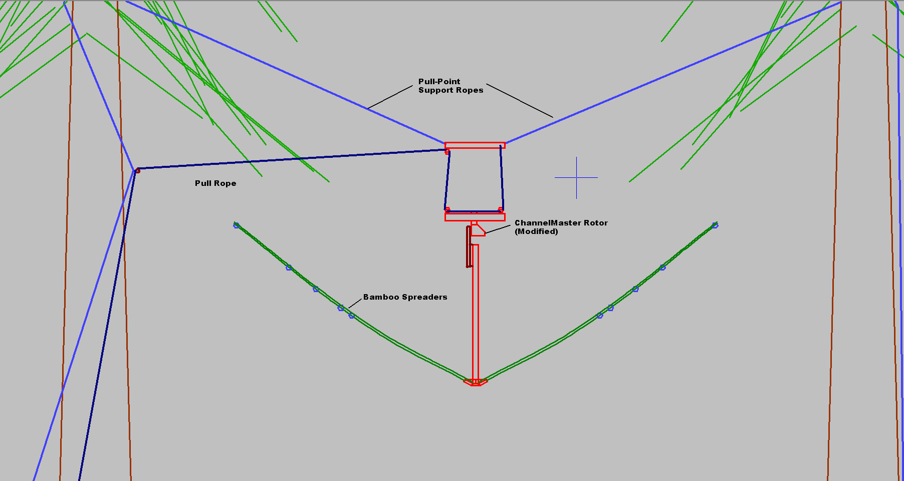
The figure above shows the first method used with the rotator pulled into the trees on the support ropes and the antenna pull rope going straight down through the center hub.
Ultimately, the rigging to raise and lower the antenna and the rotator cable were persistent difficulties with the first approach. With the rotator located above the antenna, the mechanism required a long power cable that somehow must be routed to the rotator without interfering with the rotation of the antenna itself. Furthermore, the motor pulls a couple of amps of current and the wires cannot drop much voltage or the motor will not turn. The native controller for the Channel Master unit uses a crude approach to determine the pointing direction that assumes constant motor speed and drives the motor into a hard stop to determine a reference home position. I used this system for a few months, but never knew exactly where the antenna was pointed after a few moves following the “home” procedure. When one of the wires in the drive cable broke, I went looking for another alternative.
The AF6SA PWRC Controller
What I discovered was a very clever WiFi-controlled rotator control that claimed to work for the Channel Master and similar light duty rotators. Stefan Nicov, AF6SA, makes a number of very interesting products including the PWRC, the Portable WiFi Rotor Controller. This consists of a small control board with on-board WiFi chip, a motor controller that requires only 15VDC to power up, and an optional electronic compass. The controller fits inside of the Channel Master motor case and the electronic compass is designed to be mounted on the rotating shaft above the motor. This was the best $200 I’ve spent on antenna hardware.
Nevertheless, there were a few learning experiences before things settled down. I could not find a good operating voltage even with a run of #14 wire that would not cause the system to lose connection when the rotator ran into its hard stop and the current jumped up. Even with almost 100 ft. of wire, it was hard to route it in such a way that the antenna would not hit the power wire when rotating. Although the electronic compass needs to ride along with the motor housing, leaving it inside the housing didn’t work because of the magnetic fields generated by the motor. Finally, in order to service the rotator I would need to drop not just the antenna but also the main supports that held the rotator up in the trees.
A New Plan
The figure above shows the rigging necessary to lower the rotator with the antenna. The pull rope could no longer go down the center without interference when the antenna turned, so it was routed to a auxiliary pulley tied to one of the support ropes.
The key to making the new rigging system work is to power the rotator motor via the antenna coax feed line. Rather than require the coax to supply >2A of current to the motor, I added a small Li-ion battery in the motor case to handle the peak current requirements.

The photo above shows the Channel Master motor housing ready to accept the AF6SA PWRC control board and a Li-ion battery. The blue shielded cable is for the compass and the wires with the ferrite RF chokes will connect to the antenna feed point.

Here is the the rotator pulled up and doing its job.
The compass was attached to the antenna in its own little box away from the motor magnetic fields where it now tells accurately where the antenna is pointed.
This system has worked fairly well and for several months now. I did have to repair a flaky connection on the controller board caused by a cracked solder joint that undoubtedly came about because of all the messing about I’ve had to do with various configurations. I added a 5A fuse to the battery for good measure to protect both the battery and the driver MOSFETs.
The only issue remaining is a software one. This suspended antenna is not very rigid, so when starting to turn, it takes a few moments before the antenna actually starts moving. The software like to think that it has “Stalled” and hit a hard stop. This causes the software to stop the motor and reset the location of the “Hard Stop.” As a result, I am pretty much only able to use the CCW and CW buttons to move the antenna, since the “Hard Stop” is assumed to be almost never where it actually is, and the motor will turn the wrong direction half the time.
Nevertheless – this is a very useable, inexpensive, and serviceable antenna system for those who happen to have a couple of tall trees and would rather not erect a tower.
