
Antenna modelers are often left with a question about how to handle baluns and impedance matching devices when using the NEC codes. Often we just ignore all of the feed nonsense and place the source right on the antenna wire to find the pattern, drive impedance, etc. You can also just reflect the driving impedance across an impedance transformer from the source so a 4:1 balun makes the 50 ohm source appear to be 200 ohms to the antenna.
Here I’m going to go a little deeper and show how you can use the transmission line modeling ability of the NEC codes to generate a number of interesting matching and coupling devices. NEC treats transmission lines as ideal elements (just the inside of the coax) where currents are balanced and the line is characterized by its length and impedance. The typical “current mode” balun attempts to use ideal transmission lines for its functioning. Ferrite cores are only there to ensure that, indeed, the currents remain balanced. A couple of figure below illustrate what is going on.
![]()
Example – 1:1 Isolation Balun
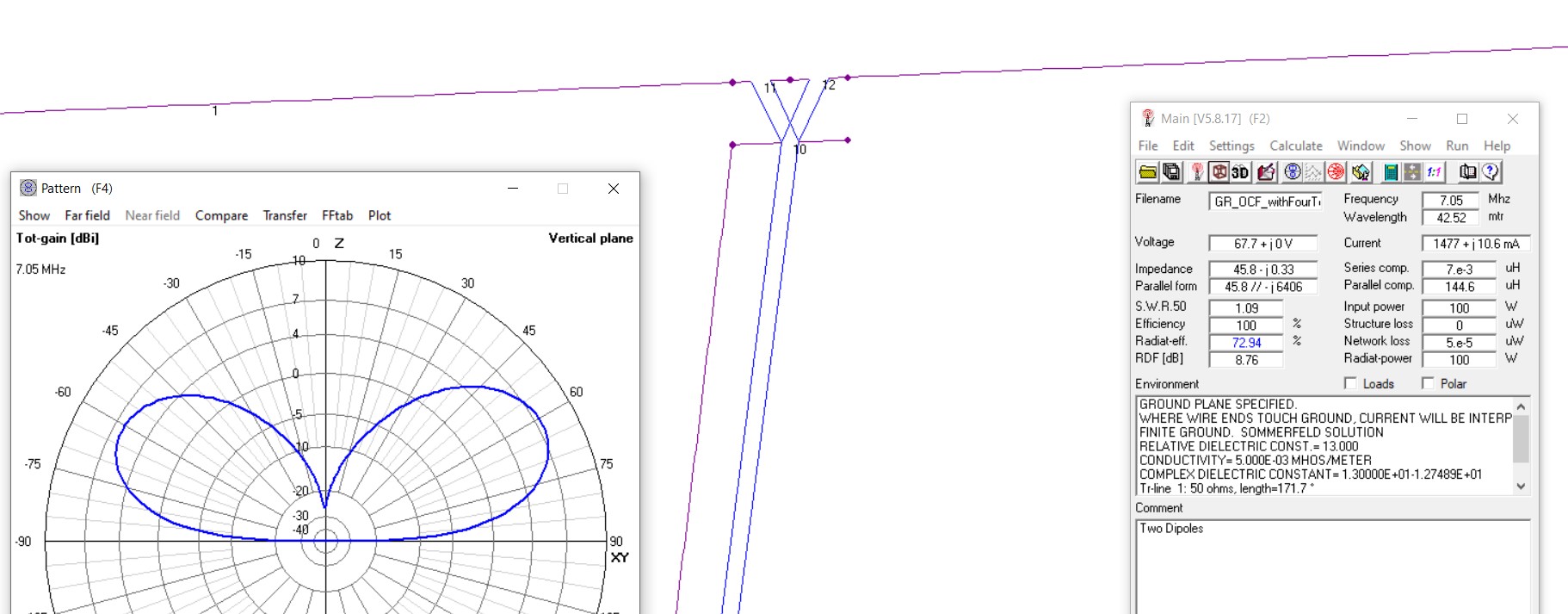
The easiest thing we can do is a 1:1 balun at the antenna. The figure below shows the balun model and connections. Segments 10 and 11 are the ends of the transmission line that make up the balun. Segment 12 connects an inductance equal to the winding inductance of the wound transmission lines across the balun which allows common mode leakage. To complete the antenna, dipole wires are connected to each side of segment 10 and a transmission line back to the radio is connected to segment 11. That feed line has both an ideal transmission line back to a 50 ohm source and the coax shield is represented as a wire that is grounded near the source.
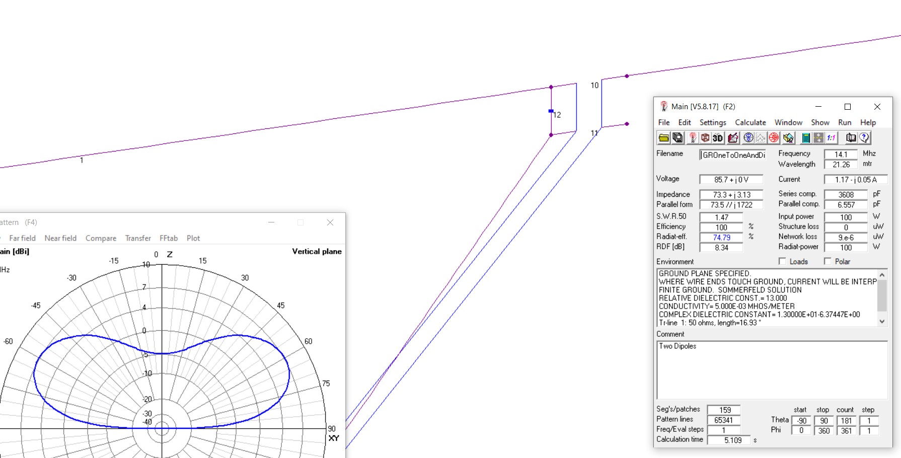
We can see the effect of the balun by either specifying a nominal value for the winding inductance or by making it very small (not there). The figures below show the currents on the antenna and the feed line in the two cases.
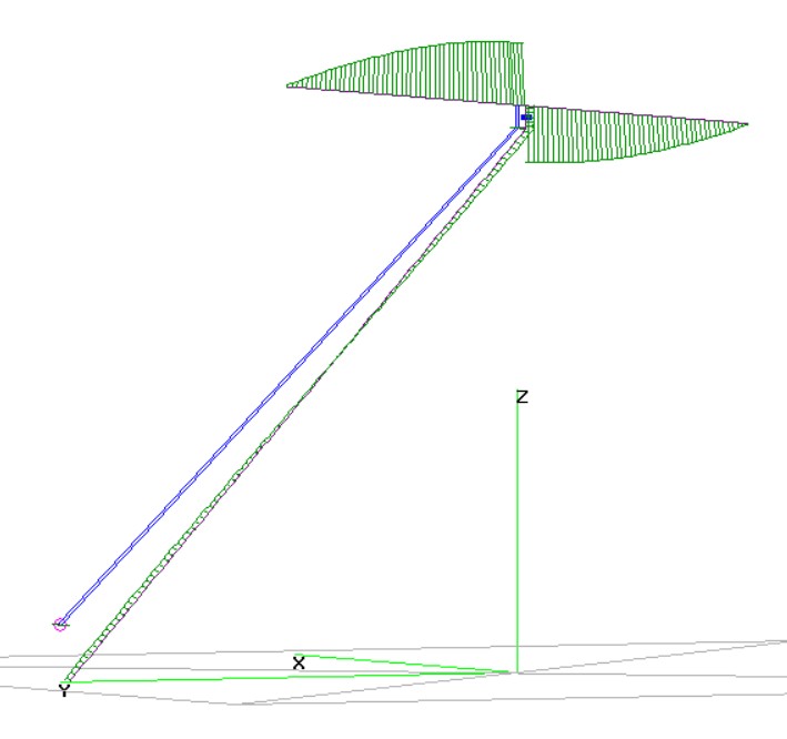
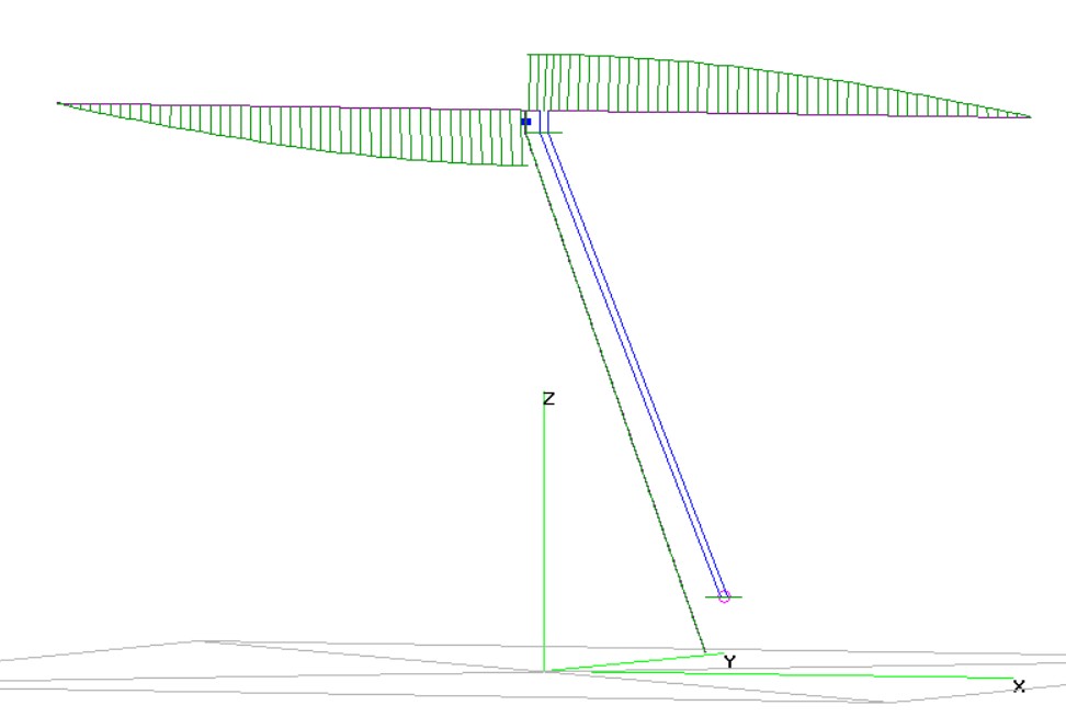
Feed line currents are apparent when the balun inductance is made very small (right figure).
As far as the model is concerned, it doesn’t care about the physical length of the transmission line elements. You can make the balun model quite small as long as you keep the segment lengths greater than 1/1000 wavelength. I parameterize the balun location and a “small length” parameter in the model so that the description is portable and can be easily scaled for desired wavelength of operation.
Example – 4:1 Matching Balun
One of the most common matching devices is the 4:1 current balun. This is nothing more than two parallel transmission lines that are parallel connected at one end and series connected at the other end.
The figure above shows the connections for a 4:1 matching balun. Segments 11 and 12 are in series and are the connections for the output end of the two transmission lines. Segment 10 serves as the parallel connection point for the two balun T-lines and the feed line from the source. A match at segment 10 would imply that the two balun transmission line windings would have twice the impedance of the feed line. In practice this can be accomplished using parallel wire line (such as zip cord). The effects of such a mismatch will be felt more as the length of the balun transmission lines approach a good fraction of the operating wavelength. For short lines typical of transformer windings, the mismatch will introduce a small inductive (too high impedance lines) or capacitive (too low impedance lines) component at the termination.
One of the assumptions with the transmission line model is that there is complete voltage isolation between the two ends of the transmission line elements. This is true to a good approximation when each line is wound on its own transformer core. However, if the two lines share the same core, then you are imposing the same potential difference across the windings; that’s what the mutual coupling will do. The enforced pair-wise current balance, implicit in NEC transmission lines model, would not be enforced if the two windings were on the same core.
The model shown does not include any parasitic shunt inductor, but they could be added similar to the 1:1 case. This ideal case without the loss path shows that even with an ideal balun it is still possible to end up with RF on the feed line.

The RF current on the feed line is zero at the feed point, but the antenna’s radiated fields induce currents in the feed line anyway. A common mode choke halfway down the feed line would solve that problem.
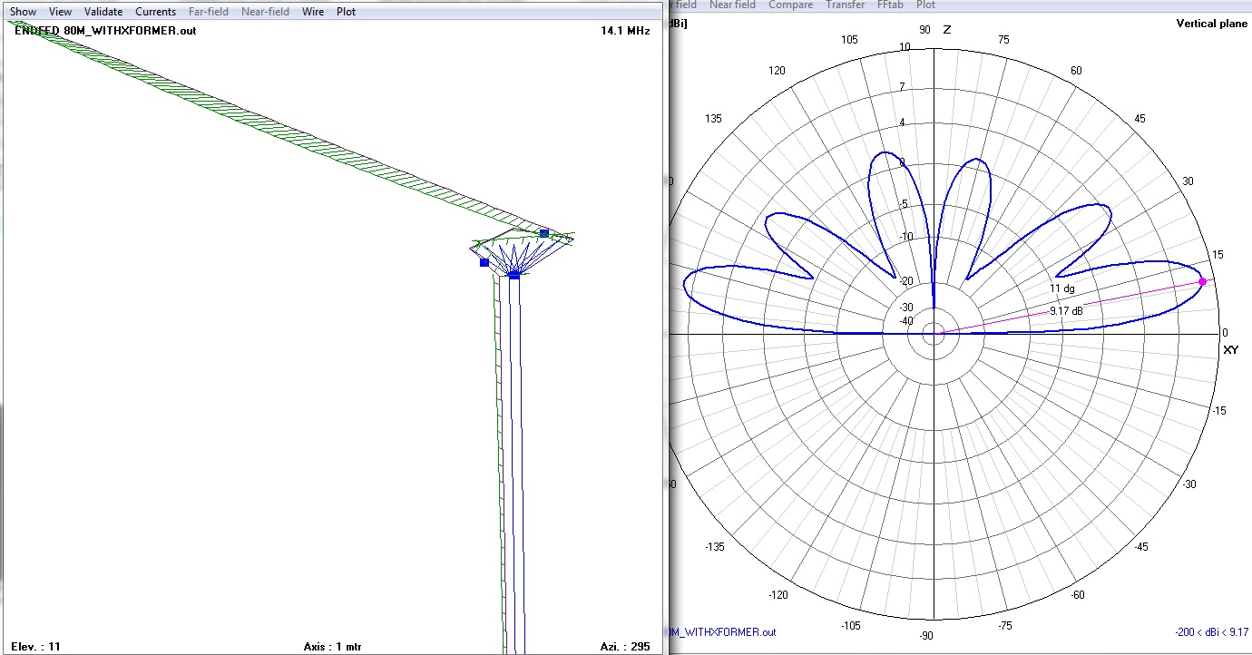
Example – 49:1 End-feed Transformer
Why stop at 4:1? No need. You can extend the parallel to series idea to build 9:1, 16:1, 25:1, etc. impedance transformers where the transformation will be the square of the number of lines you are combining. A popular ratio is 49:1 to feed end-fed multi-band wire antennas. Much magic is attributed to these high impedance transformers, often run without a “counterpoise” so it might be educational to see what the models say about this.
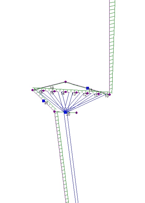
I modeled this similar to the 4:1 and included some parasitic loads to be able to see what non-ideal elements matter. The biggest question is how to deal with the “low-side” of the secondary. You could leave it floating (in which case there really is no “counterpoise”), you could connect it to a counterpoise wire at that point, or you can connect it through a “load” (segment 21) to the ground side of the input cable. I opted for the latter case, as this is what is conventionally done with these transformers. The load can be made essentially zero (as modeled), or could represent a primary inductance, depending on how this was physically connected in real life. The parasitic elements includes a capacitance across the feed line and one across the entire winding series-connected secondary.
In the 4:1 case we argued that impedance of the individual lines should be twice the source cable impedance so the combination in parallel would appear matched to the cable. With seven parallel windings 350Ω becomes impossible. Tiny wires and large spacing between conductors doesn’t work winding on a torroid. In the model, one can explore the parameter space of line impedance and electrical length for the non-matched case and see what matters.
Playing with antenna models using this transformer, it becomes clear that the impedance step up will force small currents down the feed line counterpoise. There is just no way this cannot happen. The currents need not be large if the feed section is not resonate, but they will be there.
Example – Inverting Isolated Power Splitter
This last example is the reason I looked into all of this in the first place. If one would like to drive multiple antennas from a single source, the details about what happens with the feed line, reflections from mismatched antennas, and interactions with a splitter and the transmitter all are just a bit much to wave your hands at — especially for multi-band designs.

I urge the curious reader to explore the references at the end for more details and examples of wide band RF transmission line devices. Figure 10 from the second reference shows how you can build a power splitter/combiner using transmission lines. These are reversible design and can be used either as a splitter, taking one input and generating two outputs, or as a combiner with two inputs going to a single output. These designs offer fixed impedance on all ports and a large degree of isolation between the two identical load/source ports.
For my purposes this design has the drawback of needing a “ballast” resistor that only dissipates power when one of the two isolated ports is not a matched load. I would rather have any mismatch be reflected back to the source, but I would like to ensure that the power to each load is identical even when one load is different than the other – as best as possible. Taking inspiration from the 4:1 balun and the combiner above, I went with a transmission line design where currents in one output are balanced against the return current of the other output, and vise versa. The figure below shows the design. This is “twin traction” for the output lines. You can’t have one spin and the other sit idle because they are forced to turn together. Note that pairwise balancing of all of the conductors requires four independent cores.

The ferrite loaded transmission lines provide isolation so that either side of the output lines can be grounded. The inverting connection shown is useful for driving two phased antennas. There has to be an impedance change between the source input and each of the two outputs. You have a choice about connecting the input lines in series or parallel. I choose parallel because using 75Ω cable to the loads, the parallel combination is 37.5Ω and relatively close to a 50Ω source. In practice, an antenna tuner could be employed between the splitter and the transmitter to aid in the match.

This is all pretty easy to model in 4NEC2. the diagram on the right shows the model elements. Source is on segment 20. Two parallel lines terminate on segments 11 and 12 respectively. Connections to the output lines are made on segments 13 and 14. The ferrite loaded lines allow ground connections, however desired, on the lines to the antennas. By reversing the connections on segment 14 the phase on the two output lines will either add or subtract.
This is all pretty handy for generating a pair of phased antennas and actually modeling all of the interactions in the feed lines, SWR mismatches, etc. Remember that, in general, if the target antennas are not a perfect match to the line, there will be reflected waves which return to the splitter and could potentially influence the other components there connected.
Here is an example using the splitter to model a pair of phased vertical antennas. In this case, there was an electrical length difference in the two feed cables to the two antennas that was made the same distance as the antenna separation.

You can see the nice directional pattern developed with the scheme, and that the relative phases of the currents on the two vertical wires are roughly out-of-phase with each other, with phase offset slightly by the electrical length difference of the feeds. This design could be realized with a pair of pull-up verticals made from 75Ω coax line for the bottom half of the elevated dipoles, with chokes the feed cables near ground.
One can imagine combining the various baluns and transformers I’ve discussed here for more sophisticated designs. Combining pairs of 49:1 driven end-fed antennas comes to mind. For those of you interested in using these transformer elements, you can find a compilation of the 4NEC2 files I used in these examples here: Baluns NEC Models
References
- Raymond A. Mack and Jerry Sevick, Sevick’s Transmission Line Transformers Theory and Practice 5th Edition. 2014, SciTech Publishing.
- Andrei Grebennikov, Power Combiners, Impedance Transformers and Directional Couplers, High Frequency Electronics, Dec. 2007.

Thank you, Gary!!
Although you are over my head much of the time, I appreciate and enjoy your articles, especially the ones you did on the 751A, which is what I use.
You obviously have the great gift of comprehending the math of electronics and antennas.
73, Stephen Miller KI7HJA St Maries, Idaho
Hi Gary,
Thank you for taking the time to write up this article. In searching for modeling baluns in NEC, this is the only article I could find. However, I am having a very hard time following any of the examples. I am trying to model a 4:1 balun in 4NEC2 that is being used to step down the impedance of a half-wave folded dipole, that is part of a 42-element RHCP Yagi antenna. So, I want to just copy your example for the 4:1 balun, but I am failing to see the mapping between transmission line elements in your screenshot (and the NEC file attached to this article) and, for example, the diagram on this StackExchange post:
https://ham.stackexchange.com/questions/15597/trying-to-understand-the-work-of-41-coax-balun
It looks to me as though the ground and signal portions of the second TL connecting tags 10 to 11 are backwards–it appears as though one side of the dipole (tag 1) is grounded.
Am I wrong about this? How would one model the 4:1 balun in the StackExchange post in NEC2?
Thanks.
The transmission line models in my example were assuming “short” transmission lines compared to the operation wavelength. Isolation between the ends of the transmission line is accomplished by ferrite-loading the line. The narrow band transmission line transformer in the stackexchange article could be model quite simply as well. In that case you are going to need to add two short segments in series between the ends of the antenna feed point. Between the two new segments you will want to connect a half-wave-length transmission line of appropriate impedance. On one side you would connect the input transmission line in parallel with that half-wave section. As in my examples, if you want to model common mode effects, you would need to add a wire from one side of the input transmission line back to ground to represent the “outside” of the coax shield. Good Luck!