
I have a nice off-center-fed dipole (OCFD) antenna that is my mainstay for multi-band HF work, but I would like to understand it better. With a wire antenna tied to trees it is not a simple matter to quantitatively determine the antenna’s radiation pattern experimentally. One way to get a handle on this is to compare signal levels against an isotropic antenna. Vertical antennas are nice this way, since you just need a wire straight up in the air and you naturally get an azimuthally symmetric pattern. This was my motivation to build a vertical dipole.
When you look around at how people put up vertical antennas, most of the talk is about radials – how many, how long, raised versus buried – so it goes. My gut feeling is that all this effort is misplaced. The problem with vertically polarized radiation is that when the EM wave impinges on ground it induces “radial” currents. If the antenna is close to the ground we can provide radial wires so the RF currents can return, a counterpoise for the currents in the 1/4 wave vertical section. I have tall trees. This means I can just pull the vertical antenna up into the trees so that the EM wave isn’t centered on the ground plane. I’d rather not launch a wave into the ground anyway — I want the wave to propagate across an ocean or two! Traditional verticals with radials will have the same problem with the EM wave propagating near the ground surface once the wave has moved past then ends of the radials, so why spend all of this effort on connecting the antenna into the ground for a few meters when you can’t do it for the next 1000 km anyway?! As soon as I pull the antenna up into the trees by at least 1/4 wavelength, I can now have a vertical dipole if I drop a wire from the feed point back toward ground. But rather than using another wire, realize that I already have a wire coming back down from the feed point, namely the outside of the co-ax feed itself. The important thing to do is to define the end of that radiating segment for RF, so there we place a choke. That’s it– our feed-line coax with a choke about 1/4 wavelength from the feed point and another 1/4 wavelength wire continuing on up — pretty easy!
With 4NEC2 I model because I can. This simple antenna system is a great sandbox for learning the tricks of the NEC codes and some of the basic principles of antenna design, and to find all the pitfalls of this nice idea. My NEC description for this vertical antenna model is located here, to use with 4NEC2 available here. I’ve included some “extras” like transmission lines, chokes, and wire coating in addition to the antenna wires.
When I write the model definition I like to use variables rather than just specify fixed numbers. I try to express the dimensions as functions of things I might like to change, for example the height of the top of the antenna. I’m going to pull this thing up with a rope and I can stop anywhere. If I want to model the effect of height I only have to change one variable. Hence everything is described in terms of a few variables which are meaningful when it comes time to build — height, overall length, and the length of the top driven element, angles, etc. Besides the antenna I also modeled the feed transmission line to the transmitter. NEC does this using an “ideal” transmission line with a specified impedance and length, the “inside” of the coax where only what happens at the ends of the line matter. The outside of the coax is part of the antenna system itself, and includes the RF choke that defines the lower driven element of the antenna. I then run the rest of the feed line down to ground where NEC assumes it is grounded and which could be where the radio is located.
With vertical antennas, the ground model will have an enormous effect on the level of losses, far field radiation pattern, and gain. For comparison purposes, I use the 4NEC2’s “Average” “Real Ground” model. You will discover that it is difficult to get more than about 50% radiation efficiency with this model – but that is life with a vertical antenna!
Now for some question we might hope 4NEC2 can answer.
- How much gain will this antenna give me?
- How high up should I pull this antenna?
The radiation pattern for this antenna at various heights is compared with the conventional 1/4 wave vertical antenna with buried radials in the figure below.
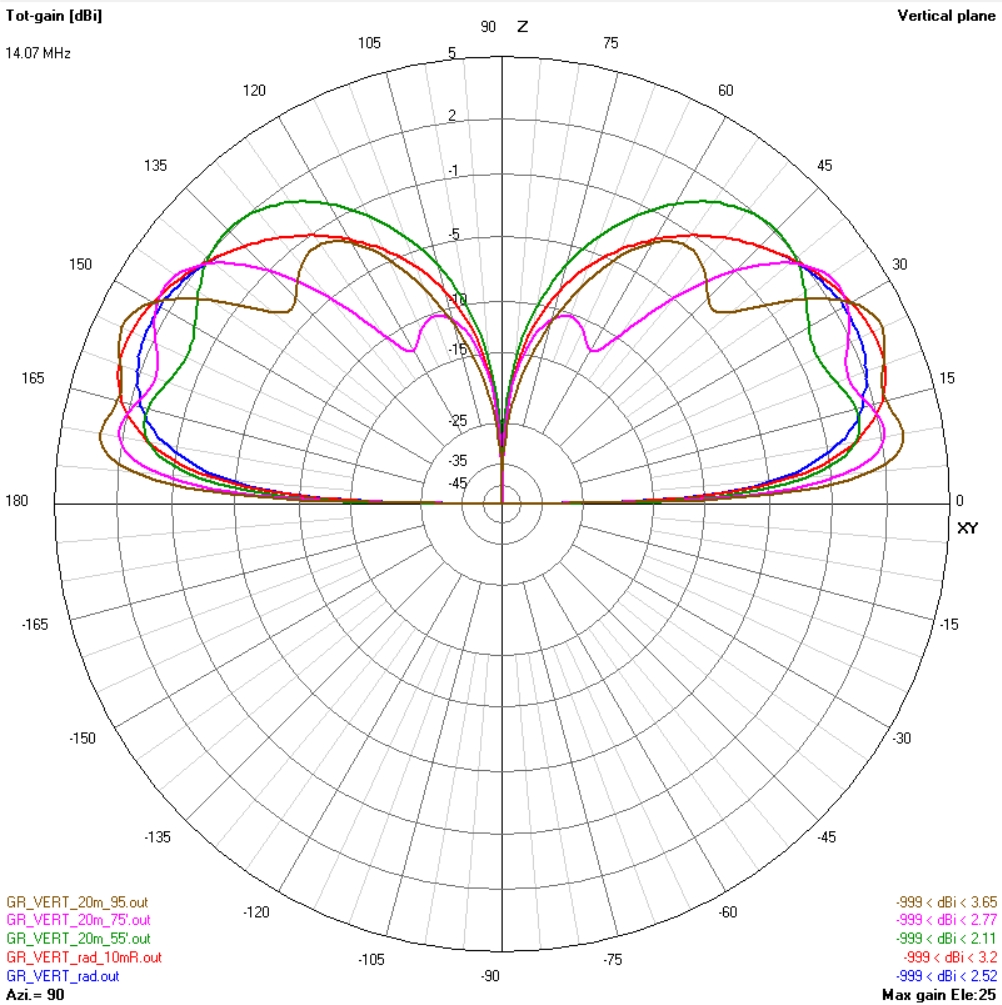
Longer radials help a little for the conventional ground-based antenna. Raising the antenna higher improves the elevated vertical dipole. The gain of elevated antennas is especially better for low radiation angles less than 15 degrees. If you have a tall tree, there seems to be little reason to spend too much time burying radials in the lawn!
- What about that choke?
The choke both defines the length of the lower section of radiator, which is the coax cable shield, and also keeps the RF from traveling down the feed line back to the radio. The more inductance the better for these tasks, but we have to build the inductor, either air-core or with ferrite, to hang on the feed line and there will be capacitance. I spent an afternoon with a few ferrite cores, some coax cable, signal generator and oscilloscope and can report that even good ferrite is not very suitable for this application. Any choke I made with ferrite was lossy and had a self resonant frequency below my desired operating frequency of 14 MHz. Much better is just a simple solenoid made from the coax feed line itself.
Unlike a simple choke on a feed to keep the RF out of the shack, the choke for this application has a much more difficult job to do. A choke near the feed point for a normal dipole is trying to choke off the RF compared to the drive impedance at that point – which may be only a 50 to 150 ohms. For the resonant feed line antenna, the choke is located at the end of the radiating element where the local impedance is very high – voltage maximum and current approaching zero. This is probably the main downfall to this antenna design because it depends so strongly on getting this choke right. If we knew the reactance of the choke we could model it with NEC. I chose to model the inductor as a parallel LCR circuit where the tuning is not perfect for the band, but the inherent Q is high so parallel R can be >20 kΩ. The total reactance of a tuned trap can be many kΩ if carefully constructed and tuned.
Figuring out the self capacitance of the choke coil took a little research. Attempts at direct measurement of capacitance are confounded by parasitic capacitance of scope probes and by resonances with the physical length of coil wires and connections themselves, so that the measured resonances do not reflect the desired stray capacitance of the coil but rather the length of wires. Internet research yielded the following formula, which seems to be plenty good for what we want. Note that the capacitance is almost entirely just a function of the coil diameter.
Cs = 0.46 * D
where Cs is in pF and D is in centimeters, good for coils with aspect ratio 0.5< l/d < 2.0. There were a surprising number of just plain incorrect quite recent theory papers on this subject, which lead me astray before finding this simple empirical formula discovered by Medhurst in 1947.

When all was said and done, I went for a about 19 feet of coax wound on a 5″ form, 14 turns. Calculated inductance is 22.5 μH with about 6.2 pF of capacitance and theoretical self-resonance at about 13.5 MHz.
Because the choke is so critical, I decided to model several different versions and mis-tunings to see the effects. If too far from self-resonance, the choke will leak RF current to the feed line and change the effective length of the radiator, which in turn, can degrade the SWR. Today I would use this Self Resonant Coil Calculator spreadsheet that I developed over the years to help design the trap coil.
To drive this antenna several questions come up.
- Should I use 50 ohm or 75 ohm coax?
- What will be the SWR? How can I tune that?
- If I use 75 ohm coax, how long should the transmission line be?
The driving impedance of a dipole in free space happens to be about 73Ω. My transmitter would like to see 50Ω. If I just use 50Ω cable to the antenna, the NEC model finds the expected SWR of around 1.5, which could be acceptable. (With a perfect choke NEC could optimize to SWR 1.4 – with a more realistic choke I could only get to SWR ~1.7). I have a large free spool of 75Ω CATV cable so I would like to show how you can win twice using the higher impedance cable. The basic principle is that the feed line should be an odd 1/4 wavelength multiple of the operating frequency. Reflections from the ends of the cable will tend to cancel each other out with this special length cable. When the cable’s impedance is the geometric mean between the input and output terminations, the cancellation of the reflected waves will be perfect! In other words, the ratio 75Ω cable / 50Ω transmitter should be the same as ZANTENNA / 75Ω cable, or about 112 Ω impedance at the feed point. We can find such a higher impedance feed point if we don’t feed in the center of the dipole, but move off to one end or the other. Notice in the model figures that the feed point is substantially below the mid-point. The numbers I came up with were 24 ft. of #14 THHN wire for the upper section and about 9 ft. of RG-6 coax between the feed point and the choke.

4NEC2 can help get the correct dimensions with the “Optimizer” that is built in. Any variables that you define, and to which you assign a value, can be used as a variable to optimize. In this case we want the optimizer to tune the wire lengths to give us low SWR. The model is set up with the 3/4 wave long 75Ω transmission line. I start off with a guess for L and L1 and let the optimizer hunt for the best values. For this antenna, I also optimize for the antenna gain at 12 degrees elevation. There are two solutions for SWR ~ 1 that correspond to the two equally off-center points of the dipole. The optimizer can converge to either solution depending upon starting conditions. The solution with the long upper wire gave slightly better low-elevation gain. The optimizer is a nice tool, but not magic! Keep in mind the physics and know what answer you are expecting before you run the optimizer. Choose only one variable at a time to begin with. Remember, too , that you do not want a design that is sensitive to small parameter variations. Experiment, but make sure you can understand the optimizer’s results based upon physical principles and you will not be led astray by numerical magic.
I just pulled this up in the tree today. Initial tests look pretty good. The SWR without additional tuning is around 1.2; signal levels average a few db less than the OCFD, which is what I expected. The uniform pattern can help, however, and I already found some DX into Kazakhstan, which is in the northerly null of the OCFD.

Great article. Might want to correct the title though, What about loss in the tree? It has been reported to be significant at close separation..
Alan, There undoubtedly is some loss driving currents in tree trunks, but usually when I throw a line way up in a tree, it never falls very close to the trunk. If you are worried about it, just pull the bottom away from the tree and you have a sloper…
Ok – in fact I have 2 tall trees and can suspend an antenna between them. Sounds like a plan!