
Mono-band vertical antenna arrays can obtain impressive directionality when built properly. These “four square” designs usually use four ground plane vertical antennas spaced 1/4 wavelength apart in a square array and fed with a carefully built phasing system. What I’m going to describe is a much simpler pull-up or mast-supported wire vertical array that gets reasonably good directional performance, is relatively simple to construct and install, does not require ground radials, and typically only drives a single radiator, the other wires acting passively. It is an antenna that should be in every serious ham’s tool box.
Inspiration for this antenna came from a contact I made with SU9VB Vladimir Bykov (home call UA4WHX), a Russian ham operating in Egypt. As usual when I make a rare contact, I investigate the operator for how I might get a contact confirmation on the QRZ.com site. This time I found a description of his vertical antennas which utilize a second element that looked a lot like one of the guy lines to the antenna mast. I was intrigued.
Vertical antennas are a good choice for amateurs looking for long distance propagation because the antenna pattern emphasizes low elevation angles that are good for going a long way. The classic “good” situation is setting up your simple vertical on a beach of some remote island where the saltwater provides the desirable ground conditions to generate lots of very low angle radiation that can be heard around the world. But simple verticals have their limitations too. The axis-symmetry implies that all directions are the same so you will hear signals and noise from everywhere, not just from where you want to listen, and your radiated power goes in all directions too, not just where you want to talk. This is what caught my attention with UA4WHX’s antenna; he found a simple way to add an extra element to a vertical to give it a bit of directivity from a single mast support.
It was time to break out the modeling program. I quickly verified that this “skewed” (because the second element has to be off at a angle compared to the sloped driven element to get the spacing right) two-element antenna works, but I also discovered that adding a third element (a second guy-wire-like element) works even better. As the modeling progressed, I could see this “tripod” antenna had real potential as a useful vertical antenna with quiet listening capability because of its directivity. Finally I realized the potential for a steerable version and went with four wires instead of just two or three. The optimized single-direction “tripod” version ends up with the driven wire and the reflector elements of a slightly different length. For a steerable version I required that all elements be identical and played with the model to see what could be done.
The Quadpod 20m Model
For a proof of concept design I decided to build a 20m version, the model described here. There are not many free parameters left once you require four directions with all elements the same length, all coming from near a single top mast or pull point, and half-wave resonant. About all that is left is the wire length tuning, the separation at the apex, apex angle of the wires, and height of the base off the ground. With the model set up I ran sweeps of the apex angle with wire length equal to λ/2.

Sweeps of the wire length compared to λ/2 show a broad range of acceptable patterns, the best coming in around 2% above the operating half-wavelength.
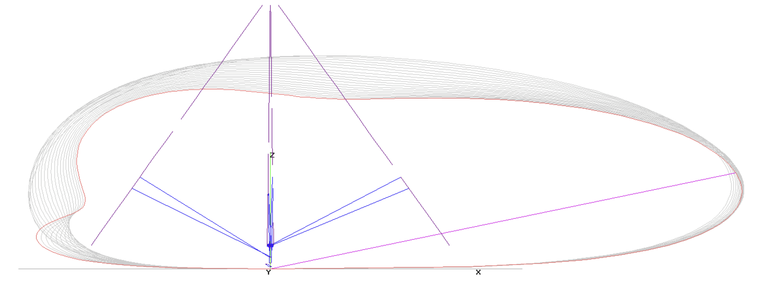
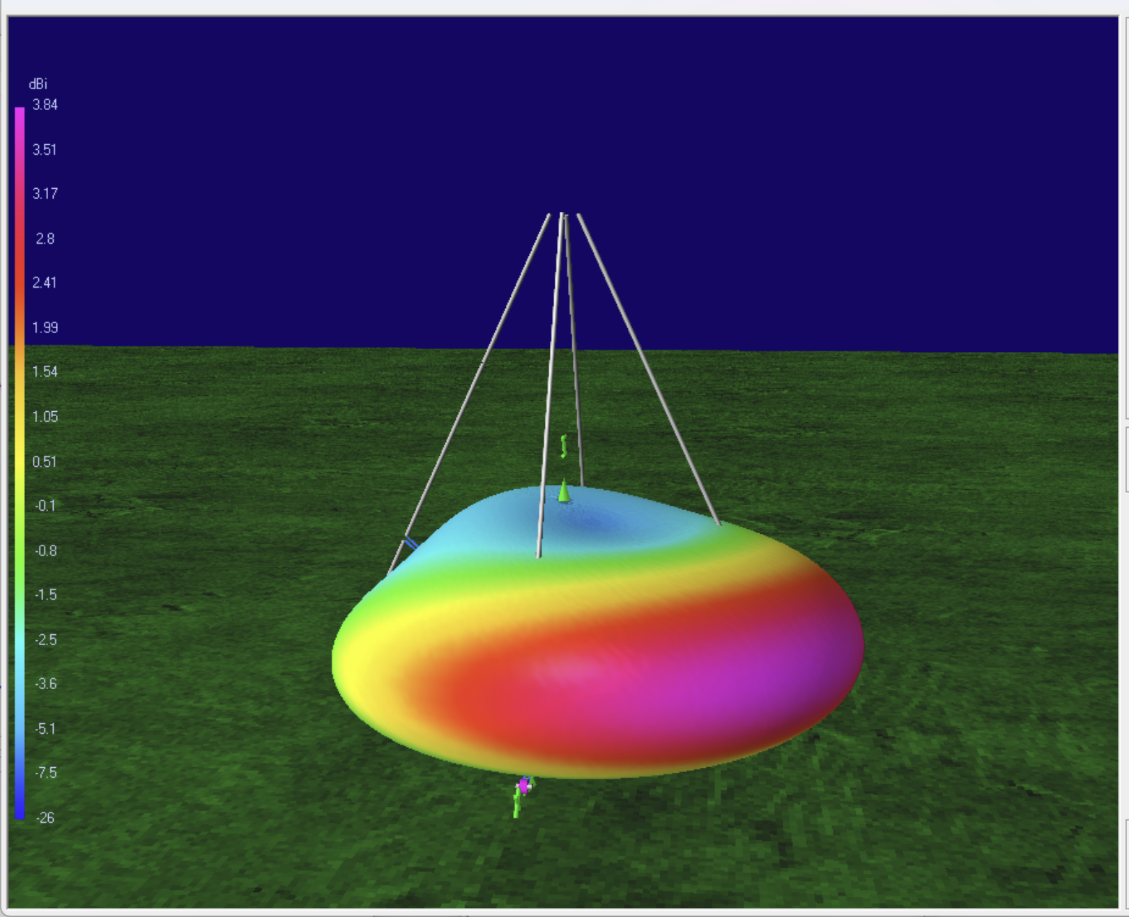
Interaction between the wires, gain and F/B is best mid to low 20’s degrees. If we pick the wire length to be 1.02 λ/2 and a 22⁰ apex angle, we get the resulting pattern.

You can see why we like this! 4NEC2 calculates the receive directivity factor (RDF) to be 8.7 dB, respectable for a listening antenna, but we get to transmit on this too! Unlike the “four square” vertical antennas, this design uses just passive parasitic reflectors in addition to the driven element, no imposed “phasing” required.
I left the wire separation at the apex at about 1 ft radius. I did some runs to look at this parameter and there is something to be gained if you can increase the wire separation to one meter radius. That can be tricky without a higher pull point or elaborate spreader structure, but can get the maximum gain to 5 dBi and RDF > 9dB, so worth considering if it is easy. Beyond a meter the benefits diminish.
So far we have avoided the question about how to drive this. We can look at the impedance information provided with a tuning curve run to get some ideas.

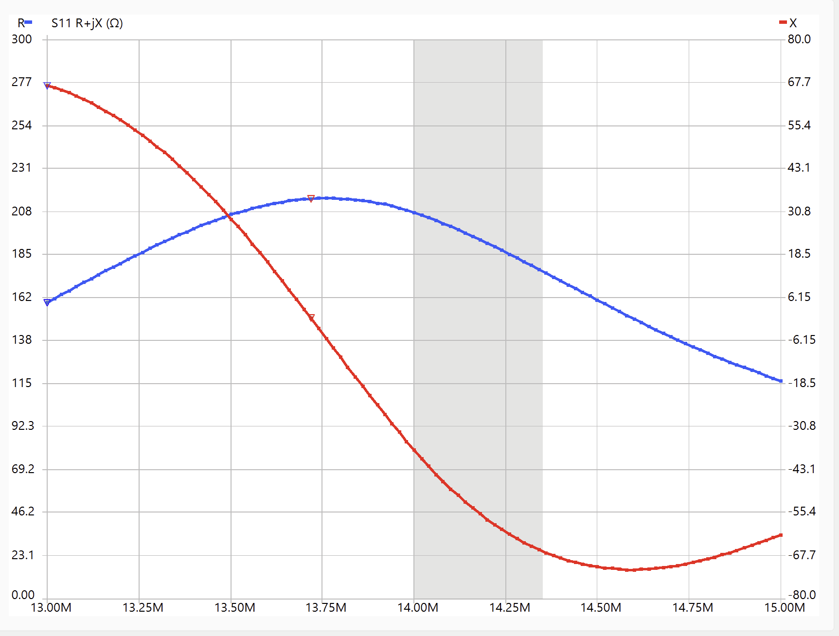
The desired operating point for the 20m simulations was 14.1 MHz, but if we look at this tuning curve for the impedance on one of the wires, notice that “resonance,” where reactance is zero, happens well below our desired operating point. What is going on here?
I took the NanoVNA out to the wires for the prototype and got the following plot at the feed point of one wire, standing on the step ladder, which is broadly similar to the model run.
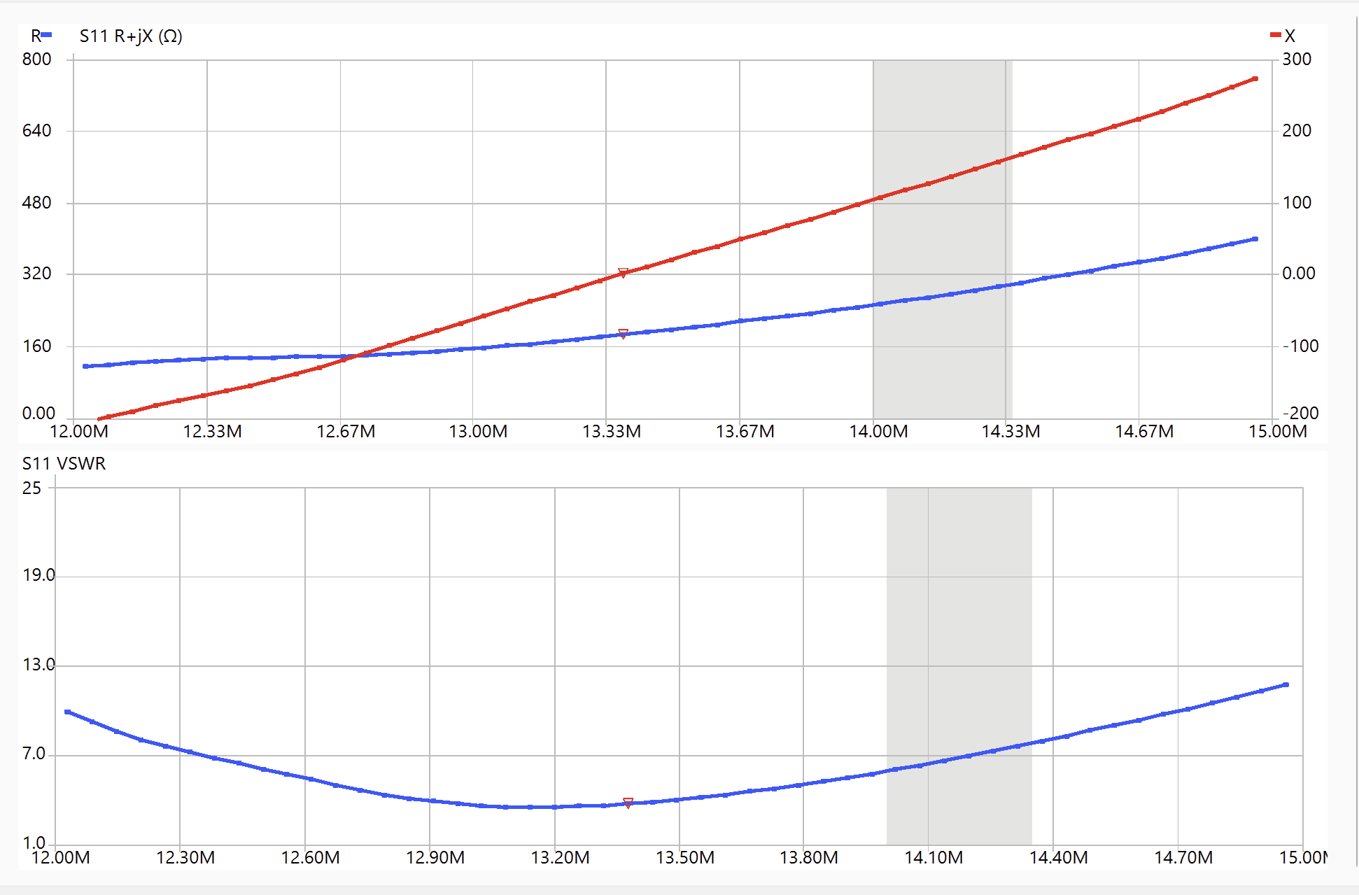
Unfortunately, when I was deploying this antenna, I saw this curve and thought it best to trim until I found resonance in the 20m band. That sent me a wild goose chase for a couple of days! Don’t do that!
My explanation for why the operating point is above the wire resonance is simply our requirement that all wires, both driver and reflectors, be the same length give rise to this behavior. The driver would prefer to be shorter for the resonance to come at 14.1 MHz; commonly dipoles are about 3% shorter than λ/2 because of “end effects”. When we impose 14.1 MHz on the driver the rest of the structure likes to resonate the way we want it to when the wires are a little longer than λ/2 by ~2%, much like Yagi reflectors like to be 3-5% longer than the driver. Operational symmetry does not allow us to have different lengths for the elements, so we will need to deal with the significant reactance at the operating point. We will come back to this.
Direction Switching
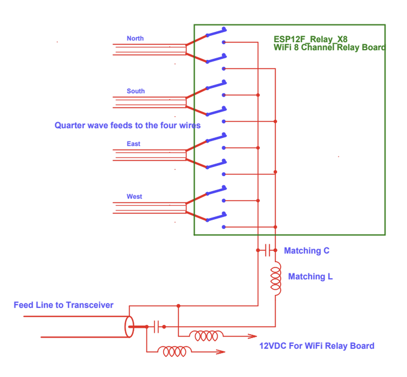
The nice thing about a mono-band design is that you can play tricks with resonances on feed lines. I happen to have a 8-channel WiFi-controlled relay board that can be used to connect the four feed points to the main feed line. (These 8-channel boards are common on eBay and Amazon and cost less than $20.) The board is powered by 12VDC on the antenna cable and controlled via WiFi over the air. The plan is to use those relays to switch feed lines from each of the wires to the main feed into the shack. The tricky thing is to use quarter-wave feeds lines to the wires. When those lines are left OPEN at the switch box end, they appear as ZERO impedance at the wire end! This lets us have the switches in one location with just a simple feed connection on the antenna wires, and the unused feed lines will not upset the pattern generation from their respective wires since the open lines appear essentially as a short circuit at the antenna wires.
With this in mind, we can trim the feeders using the nanoVNA to ensure that we get the length right. I used 300 Ω twin lead for this purpose because it was light weight and had a velocity factor near one. The λ/4 feeds all have to reach the central switch box which means the length is tight, the longer the better. I also moved the feed point down to about the 75% point on the wire, closer to the ground and hence nearer to the switch box.
Matching
As alluded above, this antenna cannot be matched just by trimming the lengths of the wires. It is broadly resonant but the driving impedance is inductive. Hence a real matching network is necessary. This was a good opportunity to become familiar with SimNEC, the powerful Smith chart calculator and circuit program that Ward Harriman, AE6TY, has been developing over the past two decades.
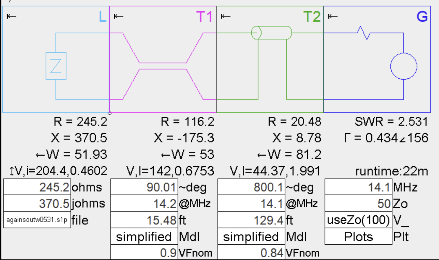
We can build our antenna and transmission model into SimNec, something like shown below. The antenna is the load on the left and is characterized by an impedance, in this case as measured by the nanoVNA on the antenna wire. Connected to the load is T1, the quarter wave 300 Ω feed sections. The switch box, located between T1 and T2 is ignored here, but it is connecting the T1 wire feeds to the cable to the shack, T2. I use 75 Ω line and need to include an accurate value for the cable length, since that matters. Finally we have the generator G which is our 50 Ω transmitter.
The SimNEC program “solves” the Smith chart equations in real time and you can scroll values and watch the impedance circles grow and shrink on the Smith chart as you attempt to generate good coupling. Cool video game!

The colors on the chart correspond with the colors of the components in the circuit. Our antenna load is in blue, the small blue circle is the “operating point” and the blue line represents a range of frequencies in the band of interest. The quarter-wave transmission line section is the pink path. Finally, the long transmission line to the shack is the green spiral. Phase advances as you move along the path. The goal is to add matching components or change parameters so that by the time you get to the generator, you are close to the center of the chart where there are no reflections and SWR=1. Rather than get too deep in the weeds, let us just note that as it is set up, we can expect SWR > 2.5, so we should do something!
After playing with this for a while I came to a couple of insights. The first was that rather than model everything, it might be better to measure the the impedance looking back toward the antenna at the switch box. If there are parasitic L or C present in the switch box, at least they will be included in whatever we measure, and the quarter-wave feed line on the antenna wire is included without having to model it. Here is what I measured at the switch box looking at the antenna with one wire switched in with the relays.
Now we can take this measured impedance sweep and use it as the “Load” definition for the SimNEC circuit. SimNEC can directly import the nanoVNA measurement files!
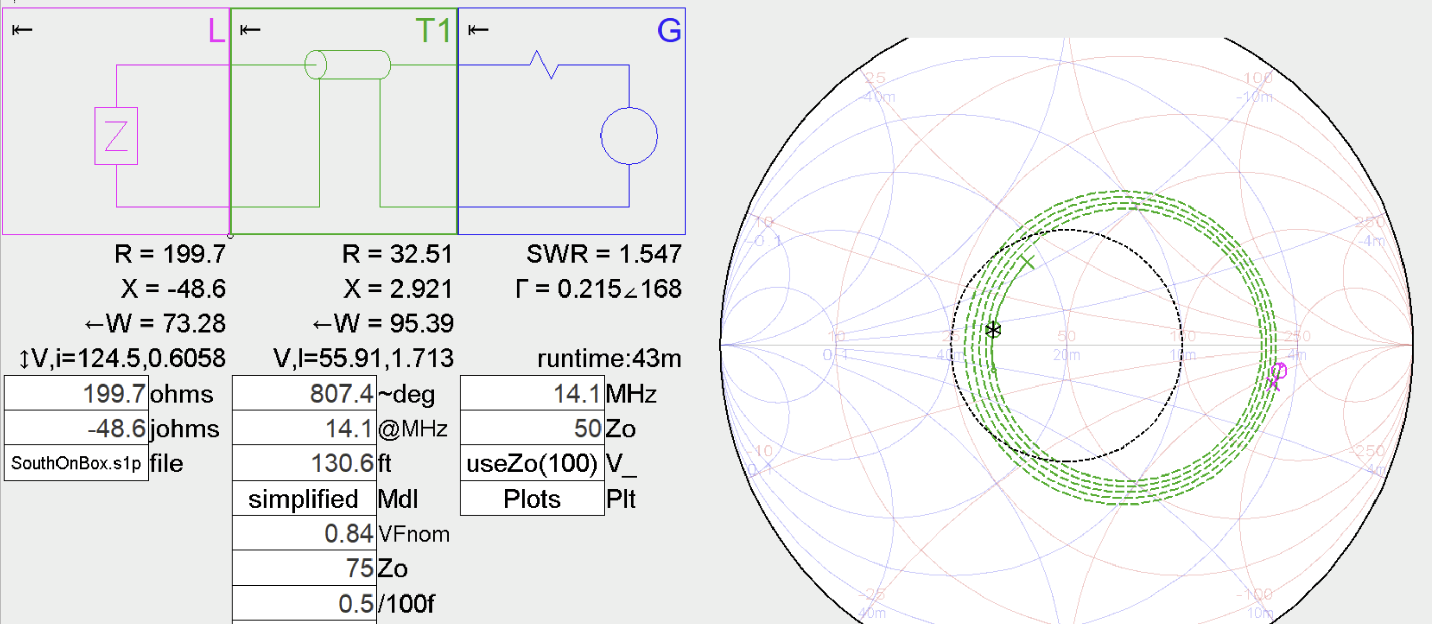
As it turns out, even without adding any matching components it is possible to get below SWR 2 just using the transformer effect of a proper length of miss-matched 75 Ω transmission line. This is what I did for first tests. If you want to design a “correct” matching network for a matched 50 ohm line, you could add the “Matching C” and “Matching L” components shown in the switch box diagram to the SimNEC model and adjust them to give low SWR. The SimNEC circuit below reflects this matching scheme where 82pF and 1 uH perfectly match a 50 ohm cable.

The tuning/matching process can be summarized as:
- First verify that the individual wires are resonant below the operating point, similar to model results, about 95% of the operating frequency. Adjust wire lengths as necessary to achieve this.
- Measure the impedance at the switch box when a wire is selected.
- Use that impedance measurement with SimNEC (or do it manually) to design the match to the cable.
Deployment

Unfortunately, antennas are difficult to photograph very well, especially in the midst of my little forest. This is the big picture. To test the prototype I used the pulley pull-up point, hanging from a branch of a tall ash tree, I have left over from the first pull-up hex beam I built. I attached the four wires of the quadpod to an upside down plastic flower pot (very top of the image) that acted as the insulator and pull-up attachment for the antenna. If you look carefully you can see a couple of the antenna wires, made from red insulated #14 THHN, glistening in the sun. The green flag-pole-arranged pull up/down rope is fastened to a classic Burning Man rebar J stake in the ground below the pull-point. On a fence post near the pull-point is a weatherproof box that contains the WiFi relay card. You can see one of the quarter-wave feed lines coming in from the North wire.
In the photos below is a better view of the switch box and the feed point attachments for the quarter-wave lines. I had some choke beads I place over the 300 Ω line wires which are probably unnecessary, but I never did test without them in place,
Also pictured is a common mode choke made with several turns of RG-6 cable through a FT240-43 core. To get good quiet performance from the antenna, it is crucial that you only hear the signals from where you want them. Simple tests measuring signal levels on just the feed cable without the antenna connected, or with just one wire of the balanced 300 Ω lines connected will show you the ultimate limits of the installation. For quiet listening you really want “connected” and “not connected” to be several 10’s of dB from one another, and that is not always easy to achieve.
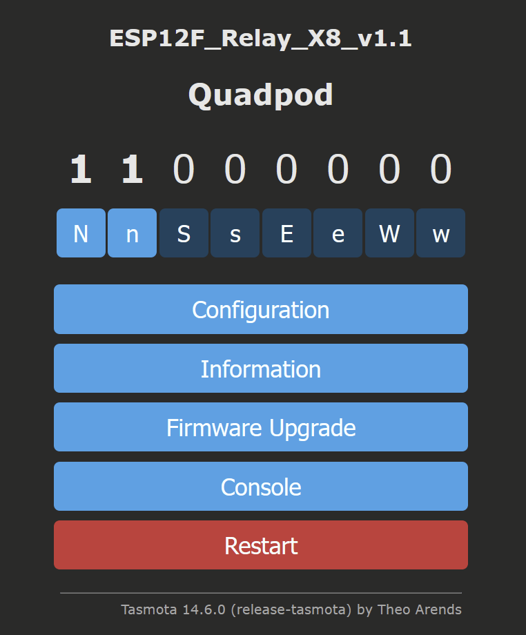
The relay board is controlled with the open source Tasmota “internet of things” firmware which is loaded on the WiFi chip on the relay card. Individual relays can be turned on/off with a click of a button on the control window in your browser. From the browser I can control which of the eight relays are closed or open. A fancier GUI may come at some point, but this is good for now.


Performance
So does it work and how do we know? Certainly we can just listen on the antenna and see if we can hear the directional nature when we switch the directions. But I prefer to compare directly with other antennas I am familiar with and to make quantitative comparisons for the directionality based on these comparisons. Fortunately I have a friend nearby, Dave Cole NK7Z, with a very good installation of a 6BTV ground plane vertical. With Dave’s assistance I collected simultaneous reception reports for worldwide FT8 signals on the 20m band for several hours. (To enlarge the multi-images below, right click on one and “open image in new tab”)
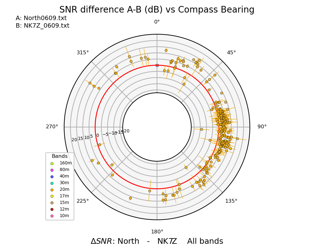
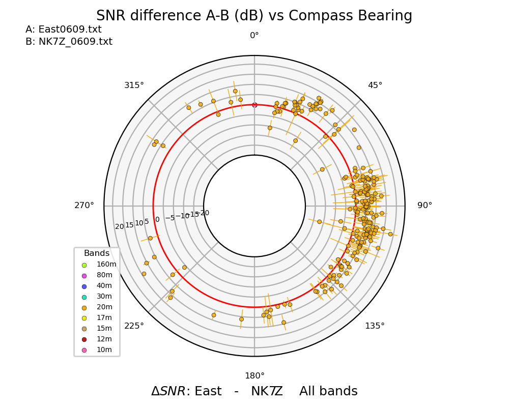


The above plots show all of the simultaneous reception reports seen by both the quadpod and the NK7Z 6BTV where the reception direction on the quadpod was switched every ten minutes to sample the various directions. Almost 20,000 simultaneous reception reports were obtained from the two antennas over the test period. The allplot program is used to process the raw ALL.TXT files. The spots outside the red circle are stronger on the quadpod, those inside the circle are stronger on the 6BTV. The grey rings are spaced every 5 dB. On average, the Quad pod does a little better than the 6BTV by ~3dB. More interesting is to use these data to generate East/West and North/South comparisons of just the quadpod using the NK7Z antenna as a reference. The quadpod is oriented 15 East of North (Clockwise) for all the wires, which should be kept in mind looking at the data.

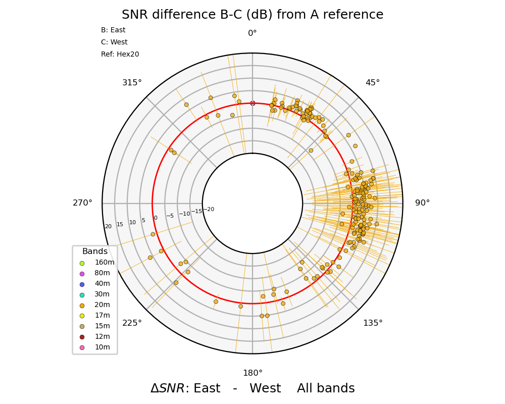
Particularly interesting here are the European stations (located due North to about 45 degrees) in the North/South comparison where there is a 10dB difference in relative strength. The East/West comparison is less dramatic, mostly comparing domestic stations to the East of us in Oregon. Vertical antennas come into their own with DX stations because of their very good low elevation angle performance that DX radiation presents. For higher elevation angle signals, as is common with domestic stations, there will be less directivity.
As a sanity check I also made similar comparisons with my very directional hex beam which was pointed North20 during the reception period. It was comforting to see that either antenna used as a reference generated very similar North/South comparisons for the quadpod.


The stations are that we are hearing much better in the North direction than in the South are the red dots. The NK7Z 6BTV as reference on the left, the AF7NX Hex beam as reference on the right.
If we look at the European DX stations we can compare directly with the both the 6BTV and the hex beam with the quadpod looking North. We find the quadpod perhaps ~6dB better than the 6BTV ground plane vertical (top left of first set of polar plots), but not surprisingly the 3 El Hex beam wins by ~5dB over the quadpod when both are looking at Europe.
There is also no substitute for listening to SSB stations while switching directions. The qualitative results are similar to what we discover with the measurements. The antenna is quietest when only a single wire is selected.

Directional noise rejection is very noticeable. Directional gain is usually noticeable, but not always. One odd report with a not-too-distant California station found that I was louder pointing North rather than South. This could be because some high take-off angles are stronger in the retrograde direction. Preliminary tests found easy pickings on FT8 into Europe, broke a pileup on SSB to Bora Bora, but could not break the SSB pileup to Bosnia Herzegovina where the hex beam had no trouble.
Variations
With four wires, besides the directions of each single driven wire, there are four more directions where two adjacent wires are driven. The driving impedance is different, and the pattern is not quite as strong as with individual wires, but eight selectable directions comes naturally with this setup. With a compromise matching you should be able to run either a single or double wire. In practice, I’ve found all eight directions to be useful.
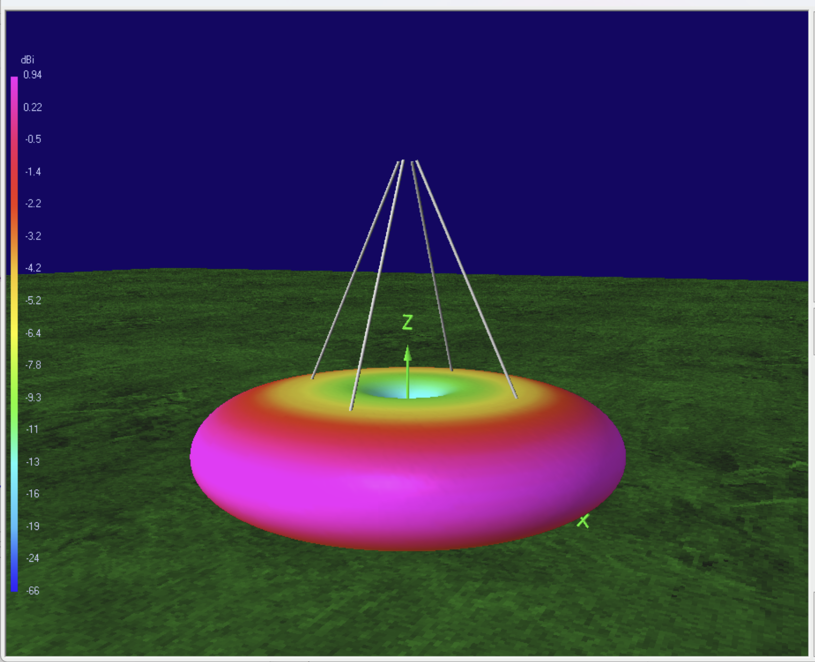
If you feed all the wires simultaneously, you revert back to the typical vertical pattern. If you don’t want to miss out on what might be behind you when you are just listening, you can switch in all the wires.
An extremely useful variation of the electrically switched steerable antenna is a simpler “tripod” design that could be set up easily and steered manually for portable work. Results of a model run are shown below.

In this case the driver wire was allowed to be shorter than the two reflectors. This made it possible to easily match the antenna to a 50 ohm load. (I again used the odd-quarter-wave 75 ohm line trick to achieve a nice impedance transformer, and then moved the feed point down to 72% along the wire to raise the impedance up to ~122 ohms where the mismatch trick works perfectly.) To deploy this in the field you would just need a pull point from a tall tree limb or a 35 ft. mast (for 20m) and three stakes in the ground to secure the wires. Where you put the stakes determine the pointing direction! There is no reason why you could not deploy wires for higher bands nested inside the lowest band wires.
And we should not forget the original Bykov design for its simplicity for portable set-ups. Here a driver and reflector are set 90 degrees from one another and the pointing direction is more or less aligned with the centers of each wire.

The real payoff for this antenna could be for the lower bands. The 40m version could be my next set of experiments since my existing pull point could almost work for the larger antenna as it is. Some tricks would need to be used to load and shorten wires for 80m and 160m, but there is certainly good motivation for looking into variations of this geometry for the low bands.
The Model
I encourage others to play with this antenna model. You can find the listing on the NEC Model Page

This model included matching components and all of the λ/4 feed lines which you can connect up in various ways just by changing the T-line end tag numbers. The feed arrangement shown here has the active wire fed from tag 35. The source is on tag 30. The inductive match component is on 36, and the capacitive match component is on 38. You can use the optimization features of 4NEC2 to find the best values for the match components if you don’t want to get out SimNEC. However 4NEC2 does not include losses in its T-lines; these components would appear as circles on the SimNEC chart rather than the spirals that include line losses.
Conclusions
Vertical antennas are noted for there very good DX performance because of their low take-off angle. However, most verticals also suffer a bad reputation for being noisy. That comes along with picking up radiation from 360 degrees around you. These multi-element half-wave verticals overcome the noise issue with good directiviity. The relatively simple installation makes the quadpod a good solution for amateurs that don’t want to invest in a full blown tower but want something better than a simple vertical. With a Spider Pole and a nested sets of wires for 20m through 10m, some clever ham who figures out the switching could have a very nice multi-band directional antenna in their back yard without a tower. In the coming years as the solar cycle wanes, the 20m band will look like the place to be. If you had to pick one band and one antenna, this is not a bad choice.

Hi
Fascinating! I’m interested in the simple portable setups for 20 m (and higher bands). What would propagation look like with just one passive reflector element? A two-wire system (one driven, one passive) would be simpler in field setup with denser vegetation or at a summit with limited space.
73 Scott VA7SNJ
Hi Scott, Then you are back to Vladimir Bykov’s design, in QRZ.com his home call page UA4WHX has some info on this antenna including some wire dimensions. It definitely works! I just included a plot and discussion of it in the Variations section just for completeness. I think it works a litter better at steeper angles than 45 degrees, but the basic idea works quite broadly for various specific shapes you can imagine for the conductor placement.