
When I jumped into the radio game with my new old Icom IC-745 transceiver, I really had no idea what I was doing. I knew I needed an antenna, so I went to a 1990 ARRL Handbook and found the “Loop Skywire” antenna which seemed like the one for me. The one resource I have is tall Douglas Fir trees, and I thought that a “Skywire” made sense hung from those trees. The ARRL article gave the impression that it was hard to go wrong, so I spent a couple of days figuring out how to hang wire in trees and get the feed line down to my radio. Turns out, the unused chimney was perfect for both supporting one corner of the loop and as a cable feed-through into the new “radio room” in the house. So I strung the wire, connected it all up and then went to try it out. To my chagrin, the transmitter balked at the arrangement and would not allow me to plow through the standing waves that were on my antenna feed. The SWR meter on my transceiver indicated SWR > 3, at which point the output circuit would refuse to give more power. So much for “hard to go wrong!”
The solution was clear — I needed an antenna tuner that would make the impedance match to the antenna feed line. I found an old Heath Kit tuner which fit the bill and solved the problem. But it irked me that I didn’t understand enough to avoid this issue in the first place.
I recently decided I wanted to compare signals from my two rigs on two antennas, and having only one tuner, I was stuck again with how to match that loop. In the last couple of months I’ve become proficient using the NEC antenna codes, so I decided to see if they could provide guidance. I use the 4NEC2 implementation by Aire Voors which is a very nice version of these venerable programs. The code has the ability to model transmission lines as well as radiating elements; it seemed it should work to figure out the feed line.
Whenever trying to use a modeling program, the first thing I do is make sure I can get the program to give me answers to a problem to which I already know the answer. That gives me confidence that I am not wasting my time doing something wrong. For the transmission line problem, I set up a very simple line with a variable termination resistance and nothing else.
You set this up in NEC with a pair of “wires” t hat are the ends of the transmission line and not connected to one another. The transmission line definition includes the line impedance and its length. One end was fed with a voltage source; the other end included two more short segments to complete the circuit, one of which included a load resistance.
I know that if this line is terminated with a resistance that same as the characteristic impedance of the line, I should see no reflections; power should all go from source to load and the standing wave ratio (SWR) should be one. If I run a frequency sweep in NEC, that is pretty much what I see.


The short wires I used to connect the load show up as reactance at the higher frequencies, but that is to be expected. The model shows SWR close to one with everything close to the 50 ohms I specified for the line impedance and the load resistance.
Now we are ready to have fun. In real life I expect the antenna to have about 150 ohms radiation resistance, and the big spool of co-ax I have is 75 ohm CATV cable. So lets run that simulation with line that is 3/4 wavelength long at 14MHz. (We will get into why I picked that length shortly.)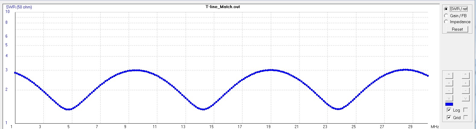
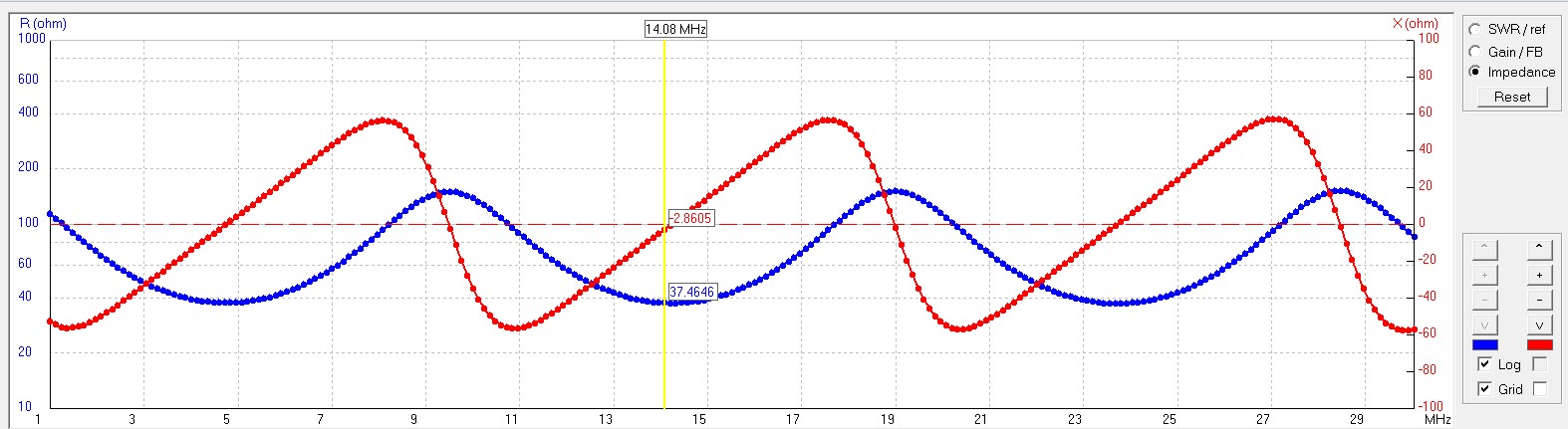
The cable is no longer matched to a 50 ohm source, so the SWR is no longer 1. But as you can see it is closer to 1 at some frequencies than at others. The impedance seen at by the source is now complex, with the real part varying between 150 and 37 ohms, depending upon the frequency.
Let’s back up and recall the physics of the anti-reflective lens coatings. This idea is simply that if you have a coating that is exactly 1/4 of a wavelength thick, then the reflections from the two sides of the 1/4 wave coating will be exactly 180 degrees out of phase with each other and will tend to cancel, so reflection from the surface will be diminished because of the coating. Any odd integer multiple of 1/4 wavelength will have this effect.
We want to do the same thing with our feed line, minimize reflections by making the feed line an odd integer multiple of 1/4 of the wavelength. I chose the length of the line to be 3/4 of a wavelength at 14 MHz – the 20m band that is arguably the most important ham band. My antenna is too far away to use just a 1/4 wavelength line. If my antenna impedance really was 150 ohms, using the 3/4 wavelength 75 ohm line would bring the SWR down from 3 to a more tolerable 1.3 by just cutting the feed cable the right length.
But what about the other bands? In general an odd integer quarter wavelength multiple for one band will not be and odd integer multiple on another band. The antenna resonances, and the feed line resonances are likely to interact in ways that are hard to predict. This is where using the NEC model really helps to extend our design beyond the single band case.
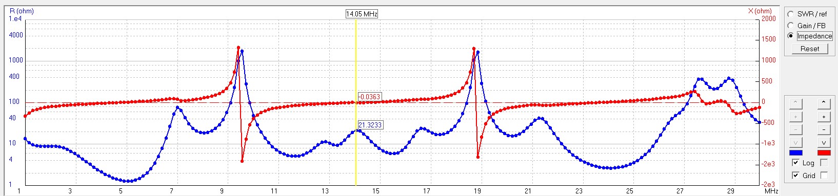
First, let us look at a square 40m loop antenna with NEC. The rendition on the right is produced by the very nice 3D viewer in 4NEC2. We can look at the impedance sweep for this geometry and get an idea of what to expect when we build something like this. The curves shown below are the SWR for a 50 ohm driver and the antenna impedance versus frequency. The resonances at the loop fundamental, 7MHZ, and its harmonics, 14, 21, & 28 MHz, are clear to see.
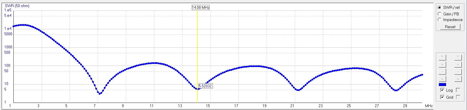

It is also clear why my first attempt to get this antenna to work failed. No-where does the 50 ohm SWR drop below 3. The advice to just “connect it up and go” from the ARRL article was just plain wrong. At the time, I also read some advice about making the feed line an integer number of half-wavelenghts in order to perfectly transfer the impedance characteristics at the antenna back to the other end of the line. If you put those two pieces of advice together, you get the following SWR sweep – much like my antenna behaved when first I connected it to my transceiver.

The curve above was generated with the model, shown in the figure to the right that includes both the loop antenna and the transmission line feed. The feed line i s modeled as a radiating wire (the outside of the coax cannot be neglected) as well as the ideal transmission line. If you look at the resonances at 7, 14, 21, and 28 MHz, you will see that indeed the half-wavelength feed (also half-wave harmonic to the antenna harmonics) does transfer the SWR at the antenna to the other end of the line. Both the model for the antenna alone and the model that includes the half-wave feed line have SWR-50 of ~3.5 at 7 MHz and ~5 for the higher bands. The antenna impedance is just too high to match well, so we are back at square one.
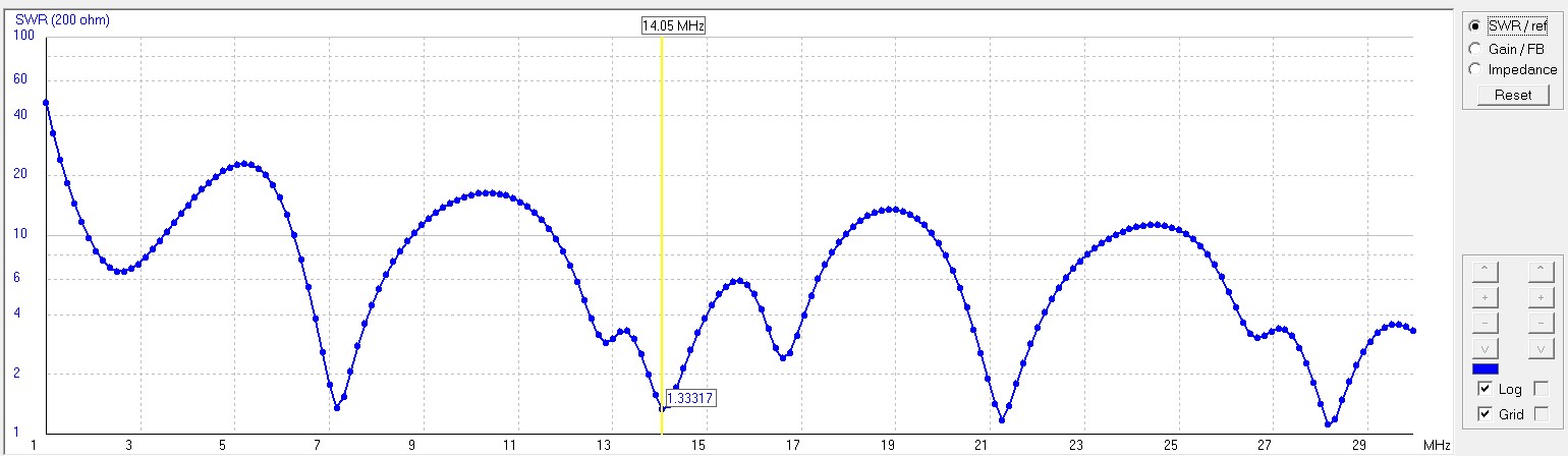
We’ve recreated the problem I was having with the model. Now let’s see what happens when we use the odd quarter-wave line length instead of the half-wave length.
Low and behold, we have tolerable SWR on all of the main harmonic bands with nothing more than chopping the feed line in the right place! Note that doing the arithmetic for all of the other bands gets complicated quickly with the interacting sets of harmonics. The simulations come into their own as the complexity exceeds your intuition about what should be happening.
So modeling and simulation are one thing. Proof is in the pudding! I put this together and measured SWR of 1.5 at 7 MHz, 2.2 at 14 MHz, and about 3 at 21 MHz, so I can easily operate on the 20 and 40m bands. However, after I went through the excercise to write this up for this blog post, I also realized how it should be done.
If you look back at the 40m Loop impedance plot, you will notice that at the antenna resonances, the real part of the impedance is between ~150 ohms and ~240 ohms for the upper bands. The best solution is to use a 4:1 impedance transformer at the antenna and 50 ohm cable to the transmitter. The reflected 200 ohm impedance will match admirably on all of the resonant bands without resorting to tricks with a quarter-wave feed as shown in the simulation below.
But back to the 1990 ARRL handbook where the construction directions for the Loop Skywire state, “connect the coaxial feed line ends directly to the wire ends. Don’t do anything else. Baluns or choke coils at the feed point are unnecessary. Don’t let anyone talk you into using them.”
What can I say — I just plain disagree! The model results don’t support such a statement nor does my experience. Using a 4:1 current balun I manged to get SWR of <1.4 on all of the resonant ham bands on the antenna. That’s the way it is supposed to work!
Update: After a few more years of experience with antenna modeling, the reader that has made it this far might well find useful my descriptions of how to model feed lines with 4NEC2 in my slide presentation, Practical Antenna Modeling, and the explicit descriptions of Modeling Baluns and Transformers with NEC Codes in the linked article.

I am not trained in antenna design but have repaired RF systems and worked on video systems.
Could this be what complicated your antenna matching issues? RG58 cable is 50 ohms, RG59 is 75 ohm cable. 75 ohm cable is typically used for video feeds (monitors are 75 ohm loads) and for cable TV signals. 50 ohm is for RF signals, RF amps are built with 50 ohm output impedance. These cables look the same to the untrained eye but also keep in mind the connectors look similar but are also different. You will see a plastic sheath inside the ground conductor of a 50 ohm connector and not one on a 75 ohm connector. The 75 ohm hardware is stocked at every Radioshack and TV store in the world, the 50 ohm is usually not stocked. This is why the wrong cable is often found on amateur radio systems. These cables have power limits so there are of course $$ RG174 and RG213 for more power.
In the systems I have worked on they use a 50 ohm cable from the amp to the antenna. A tuned transmission cable can be used to perfect the system at one particular frequency, but for multiple bands a tuning cap is put in series and another in parallel between the antenna and cable, a servo or stepper motor can be used to tune the caps in the top of the tower. Others have made a couple cap combinations that can switch in/out with a special RF relay to address only the two or three bands you may want to use but calculating the cap values may be a trick where tuning caps are easy. Also with tuning caps a wind damaged antenna can be retuned until a repair is made, with relay switched caps this is not possible.
I have found the most attenuation and impenitence distortions occur at the connectors, even the best ones. Try to avoid barrel connectors. Use one uninterrupted cable if possible. In video systems a wrong cable or connector puts a faint ghost image on the monitor, a great indicator of a reflected signal and always sends a technician to check cables, connectors and signal terminators.
If you use tuning caps there is a technique to use that is not at first intuitive. You do not stop turning the first cap when it is optimized, you must go past this point detuning the system a little. Then you adjust the other cap turning it again past the point of optimization, then back to the first cap and do the same. The reason for this is if you stop at best optimization on the cap changes in the other cap only move away from optimization and you are unable to improve from that point.
Hi Greg,
Thanks for the comment. My friend Jim also had similar concerns. He wrote to me after his comment faild to post:
Gary
I attempted to post a comment on your blog, however it thinks I live in the future. I guess Australia does do that from a West coast perspective.
But the comment was about the use of the 75 ohm cable, yes you of all people can make it work. However, wouldn’t a 50 ohm cable be a lot easier to work with, especially if you are trying to avoid a tuner?
Jim
To answer you both, indeed using 50 ohm cable makes it easier to think about the “radio” end of the matching problem — but it really doesn’t say much about the antenna end. If I was driving a diople with typical impedance around 75 ohms, then my 75 ohm cable would be no worse than 50 ohm cable. Both would deliver SWR of 1.5 with a mismatch of 75 to 50 ohms at one end or the other. The problem really is that the antenna actually has an impedance of closer to 200 ohms on the higher bands. Using 50 ohm cable would give SWR of 4! (the 4:1 balun is what saves the day!)
Greg’s method, to “tune it at the antenna” will work – but as he points out, only very well for a couple of bands. The point of my post was that after a while it gets pretty hard to keep it all in your head when there are multiple resonances in the antenna and the feed line. The simluation then really helps sort it out. With a tuner, the job is easier because you can keep the radio happy and just live with the SWR on the line from tuner to antenna. I’ll have more to say about that in a future post when I discuss my off-center-fed dipole that has yet more resonances and needs the tuner to work on all bands.
Heck, you just needed a longer wire and a bigger tin can.
Hi Pat,
Goes to show you never know who actually reads these things!!
I’m working on the longer wire!
Cheers,
Gary
For a monoband dipole fed with rg8x coax, what is the preferred feed line length ?
odd multiple of 1/2 WL ?
even multiple of 1/2 WL ?
or some other length ?
Hi Ed,
For a monoband dipole the feed impedance will be about 73 Ohms. Hence just driving it directly with the 50 ohm coax will be okay. (You may want a 1:1 balun) SWR ~ 1.5 If your transmitter is 50 ohms, then any length of 50 ohm coax will look the same to the transmitter – so any length will be okay. The games start happening when you deliberately mismatch on both ends!