The bamboo Moxon I built for the 20 meter band earlier this summer convinced me of the power of compact two element antennas. When I was showing the Moxon to a friend, he pointed up to a nearby tree and said “There’s the place to pull from,” pointing to the crotch of a tall branching ash tree in the midst of a few Douglas fir trees. The seed for the hex beam was planted. With one bamboo antenna under my belt, it seemed that doing another with the experienced previously gained would behoove me.
A survey of the pull spot, and the fact that I have no good antenna for 30 meters pushed me to try for a large hex beam that would accommodate a 30 meter element. The hex diameter needs to be about 30 ft. for the 30 meter antenna, which compact for the band, is still pretty large to fit between tree branches.
The Design
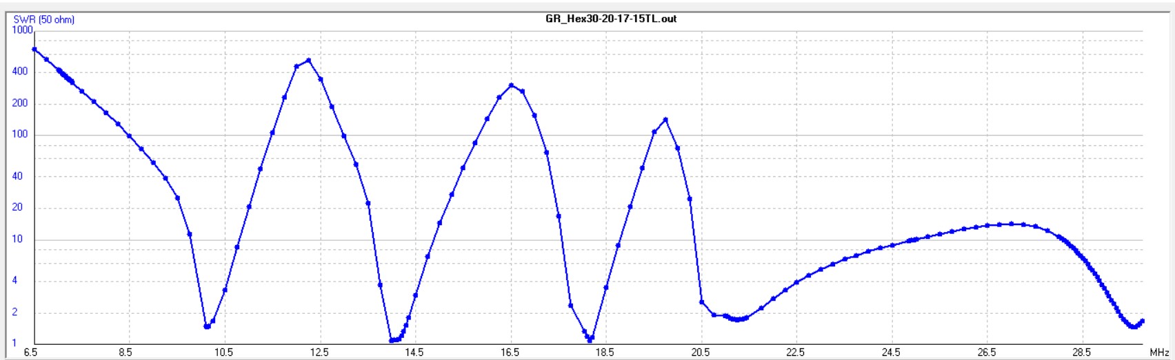
The hex beam is fairly well established with a mature design at this point. For a starting place I used the dimensions for the G3TXQ version of the hex described here by K4KIO, and of course I built a 4NEC2 hex beam model. The referenced dimensions worked very well in the model, which gave confidence to scale up for the 30 meter element as well. The 30 meter wire lengths were scaled by the ratio of design frequencies, 14.1/10.1, from the wire lengths for the 20 meter band. The one fly in the ointment for my installation is that the only good feed line I have is 75Ω coax. For this multi-band matching problem, 50Ω line is best because the hex geometry matches well to 50Ω on all of the bands. I spent some time trying to find special compensation for the lengths of the wire elements and a particular feed line length to make the 75Ω cable work, but in the end – nothing did. As is, I have to use a tuner on a couple of bands. None of this is dire, but given the choice, pick 50Ω cable. You can see the nice multi-band match that is possible in the plot below.
With the two wires and spacing between the elements, there are several parameters you can tweak for each band if you want to play with the model. After various attempts to improve matching for my 75 Ω cable I eventually returned to very close to the original element lengths. The table below shows the dimensions for the #14 THHN insulated wire I used.
|
Band (meters) |
Wire Hanger Radius (ft.) |
Length for each Driver Half Element (ft.) |
Length for Reflector Element (ft.) |
Length of spacer cords between driver and reflector (in.) |
|
30 |
14.73 |
24.8 |
46.8 |
32 |
|
20 |
10.55 |
17.7 |
33.5 |
24 |
|
17 |
8.35 |
13.8 |
26.3 |
19 |
|
15 |
7.08 |
11.8 |
22.5 |
16 |
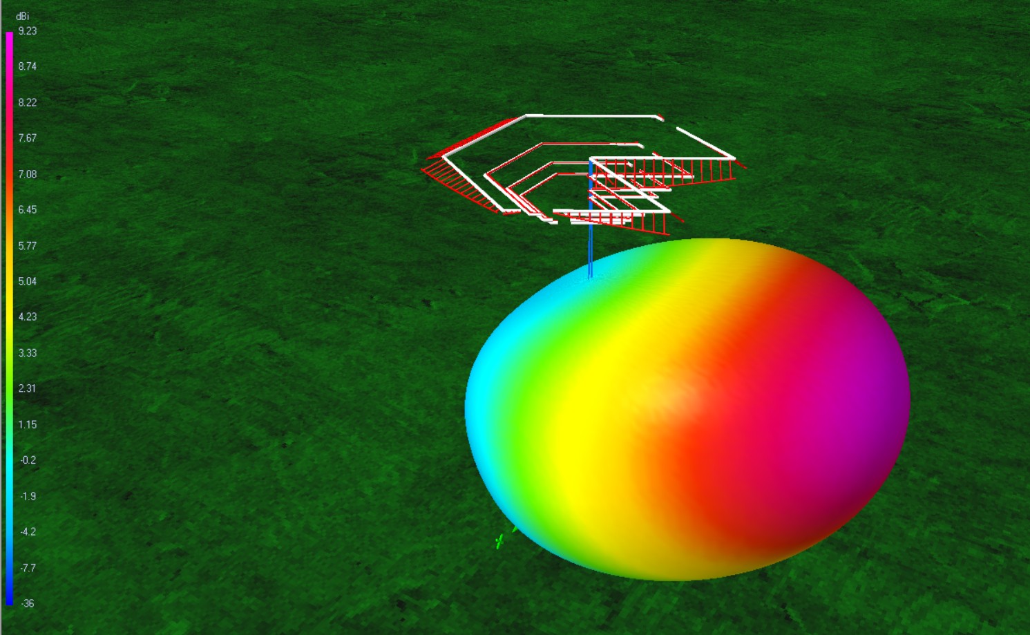
The hex beam pattern has a broad forward lobe with good front to back ratio. The upper bands will have better low elevation angle performance.
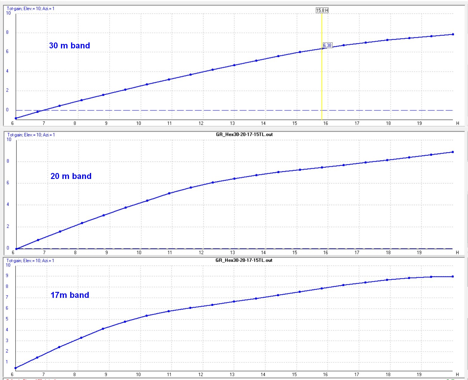
Although the pull point was about 60 ft. up in the tree, getting the antenna anywhere close to that high up among the branches of the nearby trees was not going to be possible. How hard should I try? A look at the forward gain of the antenna as a function of height off of the ground helps to distill the issue. We all know that higher is better. Particularly on the 30m band getting it up high is important. In practice, 35 ft. will probably be about the limit, but what the curves say is that every ten ft. more I get it in the air improves the gain by about 2 to 3 dB — so very much worth the effort to get it as high as possible.
Construction
The bamboo patch grows beside the house to provide a screen between us and the neighbor. Every year it provides poles for garden trellises and pushes up another couple dozen shoots. The canes get stronger after a year or two of growth so those are the ones I harvest for poles. For the 30 meter hex beam the spreader poles need to be almost 16 ft. long. I looked for the best ones in the patch that were tall, yet not too fat at the bottom.
 I made the hub from some scrap 3/4″ plywood that I had on hand. I laid out and cut the two hexagons with the table saw and then made up a bunch of triangular spacers that fit between the hexagons in such a way as to form channels for the bamboo ends to fit. The spacers were screwed to the bottom hexagon and then holes were drilled through the entire assembly in the middle of each section for bolts to squeeze the assembly together. The bamboo spreaders were inserted into each channel. I had a scrap of 2″ PVC pipe (2 3/8″ O.D.) and a 2 1/2″ hole saw to make the holes for the central post in the hub hexagons. The top of the central post serves as the anchor for the chords that tension the spreaders. A 3/8″ bolt through the PVC pipe near the top serves as the pull point for the entire antenna. The hub is suspended on the pipe and supported by a random PVC pipe fitting on the bottom of the pipe that prevents the hub from slipping off. There are bound to be better ways than this, but I used what was on hand and completely avoided a trip to the hardware store. A high performance antenna need not cost a lot if you are innovative!
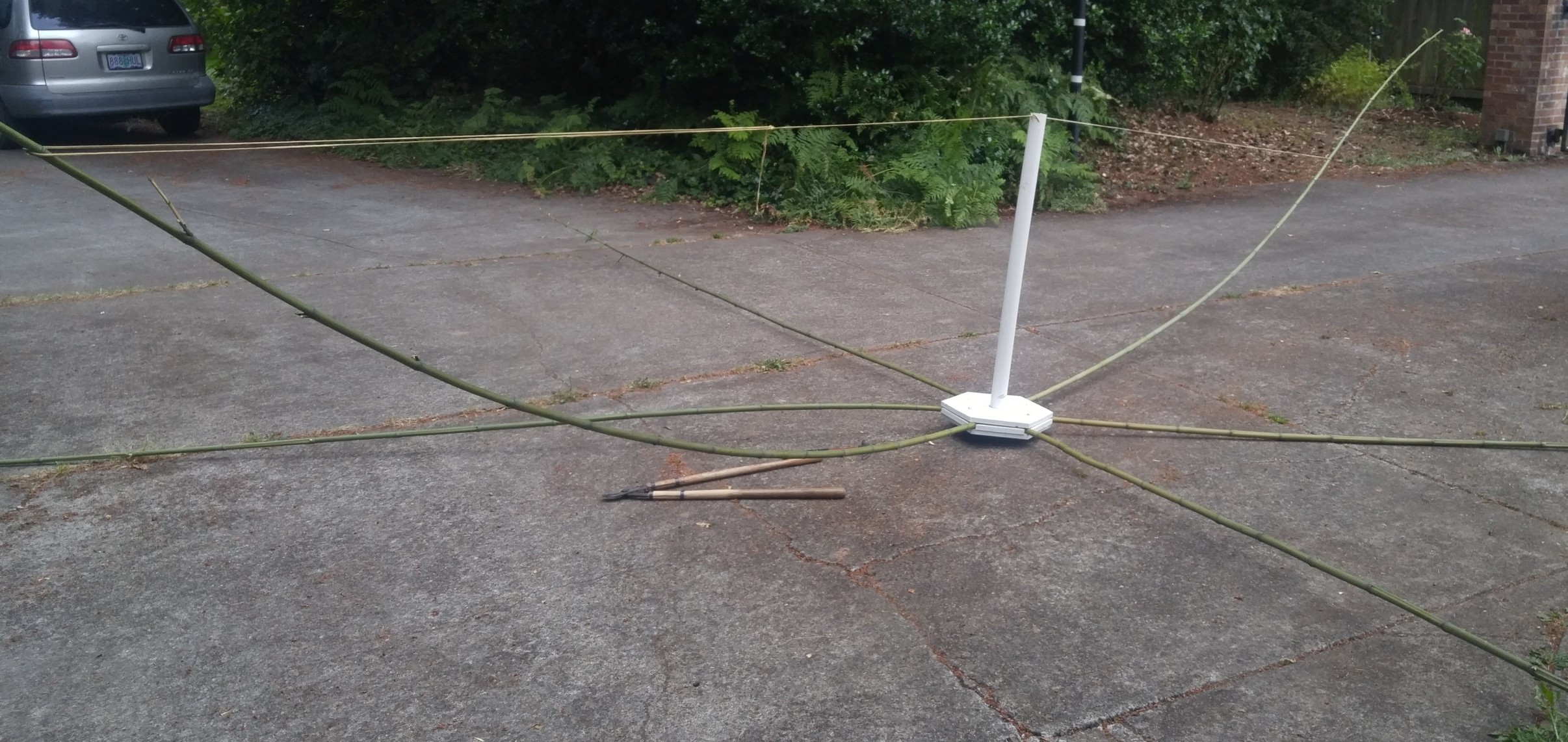
Each bamboo spreader is tensioned into an arc with a piece of parachute cord, tied from a point about three quarters of the way out pole back to the top of the central PVC pipe. I made the cords a little long and used a taught-line knot so that the tension could be easily adjusted as the building process commenced.
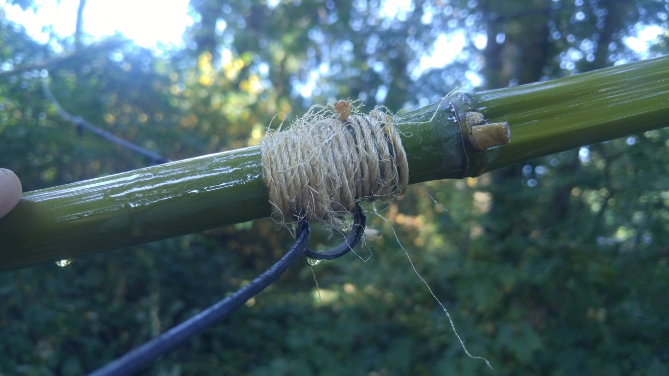
The wire hangers again used inexpensive garden materials. I have a ball of twine and I cut up a piece of 5/8 poly irrigation tubing into loops for the wire hangers. I lashed the poly loops to the bamboo spreaders at the correct location out from the center. There is not much to making these lashings; the main thing is to get them started so they do not release. if you flip the ends “under two” loops, they will lock in pretty well.
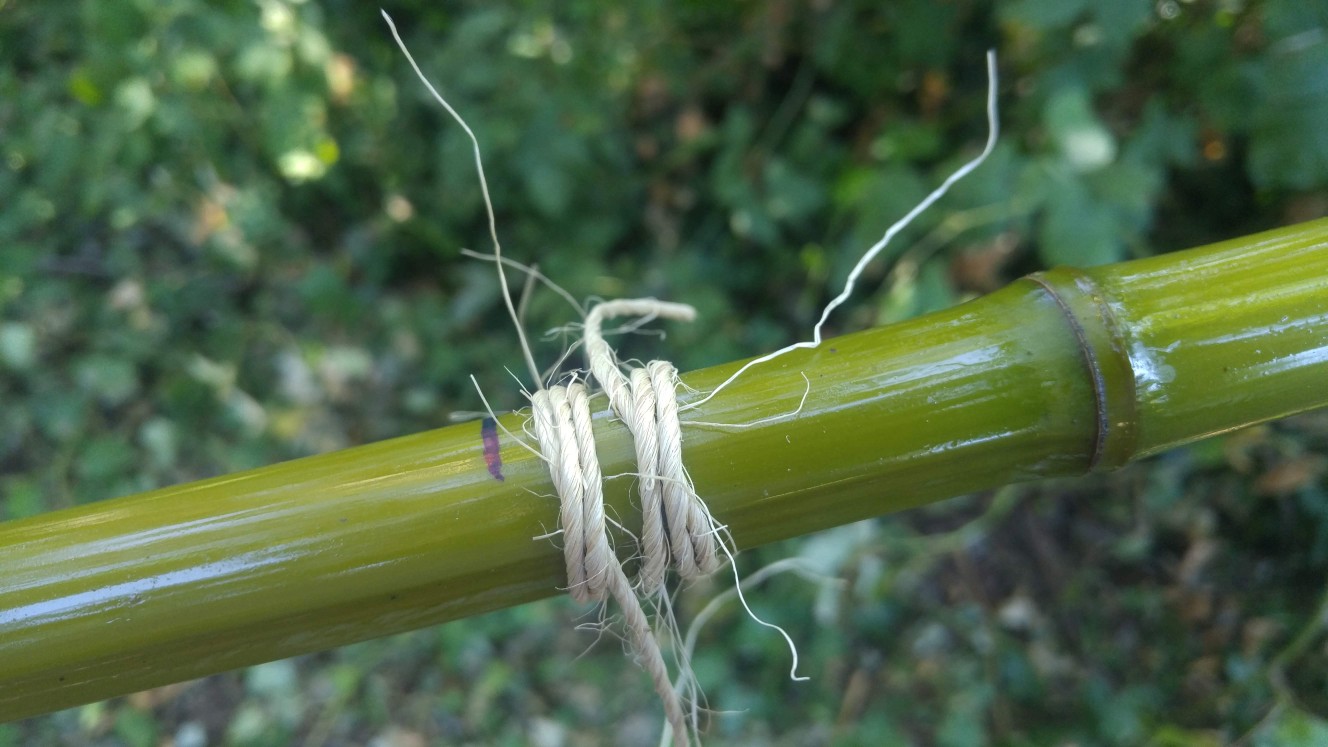
You need to install six hangers on the six spreaders for each band. By the time you’ve done the ones for the first wire you are an expert and they will start to look good. Nothing like a little practice! By the time you are done, you will likely go back and do the first few over again. If you need to, the hangers will slide along the poles to so you can make adjustments. Once I was happy with the position of everything I coated the lashings with spar varnish to protect them from the weather and lock them in place.
The wire elements are cut to length with O-lugs attached to the ends of the wires. The spacing between the driven element and the reflector is taken up with a length of cord tied between the wires, one for each half of the driven element. I drilled a pair pilot holes for sheet metal screws in the central PVC pillar at the heights for each of the bands so that the ends of the driven elements had an anchor. The wire element assemblies are threaded through the hangers with the ends terminating at the central pillar. The tension of the wires will tend to open the front facing spreaders so those two poles are held together with another piece of parachute cord.
I brought the coax feed in from the bottom of the PVC pipe through a hole in the side wall of the pipe. I used more O-lugs on the coax and on sections of zip cord that were used to connect between the antenna elements. Zip cord has an impedance of about 100 ohms, so I used two pieces in parallel between the element terminations to avoid adding too much inductance. Sheet metal screws through the O-lugs and into the PVC post made the connections.

With the antenna hanging from its pull point near the ground I gave all of the poles a coat of spar varnish. Bamboo in the garden deteriorates in the sun and rain after a year or two. I would like the hex beam to last a few more years.
Bamboo is a natural material and each pole wants to bend it is unique way. What matters for a good resonance on the band is the length of the elements and not so much exactly where they are supported in space, so you have some latitude when it comes to making it look right. After a few trips up and down into the tree branches, I found that the poles would tend to move sideways quite a bit if anything got tangled on the pull up. The solution was to loop the 30 meter wire around the pole at each tip. The poles could still be adjusted sideways, but the loop added to the stability of the shape during the manipulations needed to get the antenna up past obstructions.
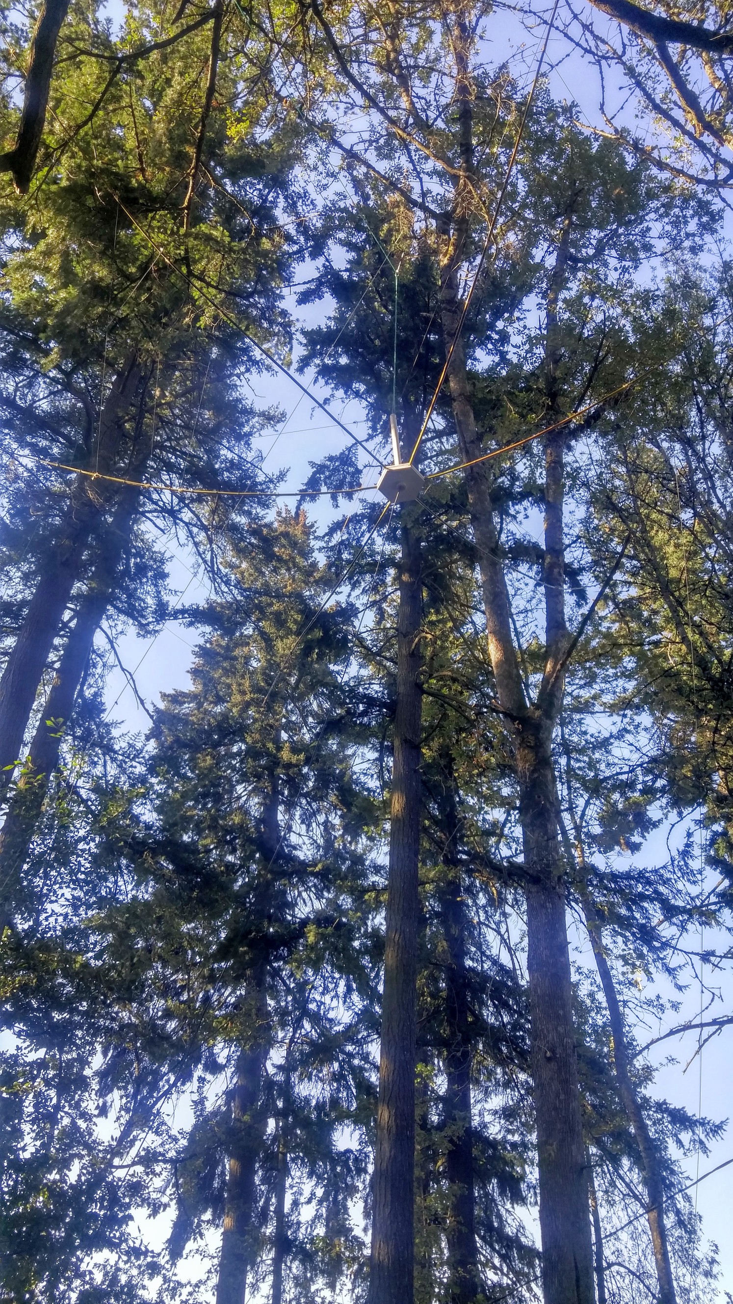
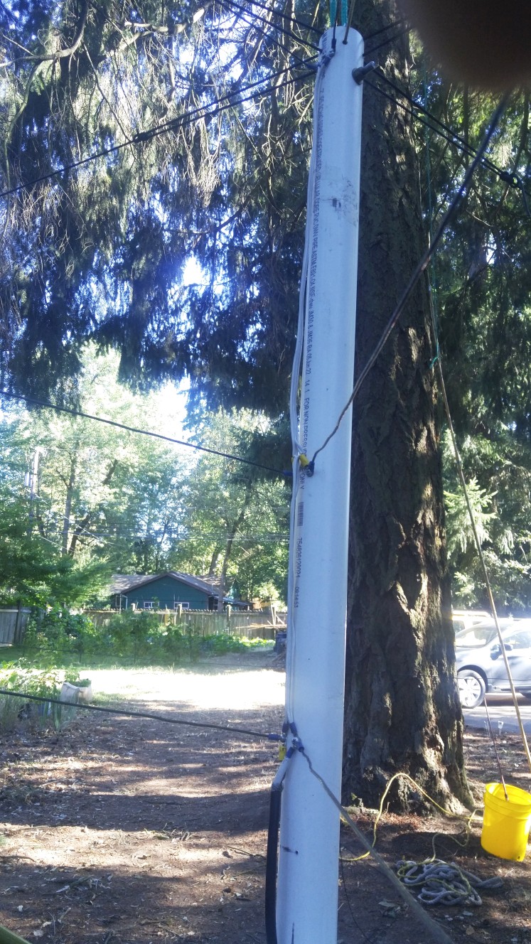
Getting the hex beam up into the trees was its own adventure. I needed to trim a few branches that were thirty five feet in the air and I was not inclined to go after them with ladder and chain saw. I devised a “rope saw” from an old chainsaw chain and, with difficulty, removed the worst offenders while standing on the ground. Still, to get the antenna all the way up takes swinging it between obstructing branches and ropes. I fastened cords to three of the bamboo poles that drop all the way to the ground so that I can tilt and pull and steer the antenna as it is pulled into position. Fortunately it clears some of the worst branches once it is above thirty feet, and the cords let me point the antenna in the direction I would like to listen without needing to lower it down.
Rigging for the pull consists of a stout rope over the tree branch from which hangs a pulley. A second pulley is attached to the pull point on the PVC pipe and the main pull rope is tied off at the upper pulley on the rope to achieve a 2:1 mechanical advantage and reduce the tension on the pull rope. If you expand the photo above you can see the ropes snaking through the branches. With the antenna up as high as it can go, the return lines on the pull ropes are bumping into the 30 meter wire. Further height would require more elaborate rigging.
Performance
The hex beam transformed my capabilities on the 30 meter band. Europe has come alive. On 20 meters, the hex beam reliably has 3 to 5 dB more signal strength than my collinear vertical, my previous best DX antenna. Even though I have some very good wire antennas, the step up to a beam has been pleasantly dramatic. I have to recommend it.

Wonderful write up and great photos, Gary. Thanks
Thanks, nice project
Did you optimize vertical distance between the different band elements?
Or just fasten the wires on the spreaders where they fit?
I consider a 30m-17m-6m hexbeam, and wonder how much vertical spacing that is needed between these bands. The late G3TXQ have some indications for other cases (http://karinya.net/g3txq/hexbeam/broadband/).
73 de Poul SA7CND
Hi Poul, You pretty much need to just place the wires where they land on the spreaders. I was surprised that the the wires for each band are quite independent of each other in the model simulations, so this is not too critical.
The antenna has been up for about a year now, still in good shape, and has really worked out well. Do they grow bamboo in Sweden?
Cheers,
Gary
Dear Gary,
nice work! :)
I have a task to make a hexbeam antenna and the default frequency is 446MHz. So, I just need coordinates of two opposite purple wires and scale them to 446 MHz.
I would definitely like to point out that when opening your drawing in the 4NEC2 program, I get the error: “NEC: NO SEGMENT HAS AN ITAG OF 51” and because of that I cannot see the antenna radiation display. Can you help me with that please?
Best regards!
Hi Victoria,
I just tested the NEC file associated with the link that gets you the gr_hex30-20-17-15tl.zip file. When you unzip, change the name of the .txt file to gr_hex30-20-17-15tl.NEC so 4NEC2 will read it. If you have further problems let me know.
As to a hex for 446 MHz, I’m sure it can be done, but a full size multi-element Yagi will give you better performance and the at the higher frequency you probably don’t care as much about keeping everything compact… Just my 2 cents…
Cheers,
Gary