A lowly coil of wire can be surprisingly difficult to understand and model correctly. I use coils of wire or coils of coax cable as trap inductors for various antenna designs that I have built. In the low frequency limit, the traditional inductance calculations work okay and can give you a pretty good estimate of a coil’s lumped inductance. However, there are two properties of coils of wire that start to make for difficulties as the frequency goes up. The first is that there is a natural resonance associated with the time it takes a speed-of-light wave to travel down the entire length of coil wire and bounce back. The second effect is a resonance between the lumped inductance and a lumped equivalent capacitance across the coil. Which effect is most dominant depends if the wire is wound in a long skinny coil or a short fat one. Even with short fat coils, you can interpret the resonance condition to be the “slow wave” double transit time for the coil of wire. We will be concerned with the first resonance, which is the strongest, but if you consider waves bouncing on a wire, you can see that there will naturally be higher harmonic resonances as well, which are not present in a lumped element analysis.
The physical transition from what might best be described as a helical transmission line for long skinny coils, to a discreet lumped inductor with a parallel capacitance for short fat ones does not really matter much from an engineering perspective. What we would like is a simple model (the inductor with parallel capacitor for the fundamental resonance) and a way to accurately determine these parameters for a particular coil geometry. The lumped circuit model is handled well in the NEC codes so we have a way to go from a coil recipe to antenna models that use such a coil. This all works well for frequencies at or below the first coil resonance. Be aware that the lumped element approximation may not be accurate at frequencies higher than the first coil resonance. For any of this to be useful to the antenna designer, we need a reliable way to build coils with the properties we want.
To tackle this problem, I’m going to start with what I think are the best empirical formulas that have been digested and expanded by David Knight. [1,2] I urge the driven reader to explore Knight’s webpages. Knight also demonstrates nicely the higher harmonic resonances that can be present on a coil of wire. His emphasis has been on verifying and improving the accuracy of inductance and capacitance expressions for single layer coils of uncoated (or thinly coated) wire. The expressions for the coil’s self capacitance are empirically determined by measuring the coil’s first self resonant frequency. Here we will use the current sheet model for inductance and Knight’s expression for capacitance to come up with a spread sheet “calculator” that can be used to design coils for a particular self-resonant frequency. Emphasis will be for short coils where the lumped circuit approximations fare best. When building an antenna trap, self capacitance can be a very good thing to cultivate, since the self resonant point can can be produced with lower inductance (and wire length) when in resonance with more coil self capacitance. To begin with, lets look at the arithmetic for single layer coils. Single layer coils have the advantage that they are well studied and hence we have the best chance that we can come up with a way to design them accurately for our needs.
Single layer coils
We start with an expression for the inductance of a coil using the current sheet approximation and corrections for magnetic fringing fields.
[1]
Where 
[2]

in terms of the number of turns and the winding diameter. Rearranging we can express the inductance compared to the coil wire length as
[3]

where 
If we call 
[4]

where 
We use Knight’s formula for capacitance.
[5]
![C = {4 \epsilon_0 \epsilon_x \over \pi}l \left[1+ k_c {(1 + \epsilon_i/\epsilon_x)\over 2} \right]{1 \over \cos^2 \psi}](https://s0.wp.com/latex.php?latex=C+%3D++%7B4+%5Cepsilon_0+%5Cepsilon_x%26nbsp%3B+%5Cover+%5Cpi%7Dl+%5Cleft%5B1%2B+k_c%26nbsp%3B+%7B%281+%2B+%5Cepsilon_i%2F%5Cepsilon_x%29%5Cover+2%7D+%5Cright%5D%7B1+%5Cover+%5Ccos%5E2+%5Cpsi%7D+&bg=ffffff&fg=000000&s=1&c=20201002)
where
[6]

and 

For the purpose of building trap coils we are interested in the resonance condition for a particular wavelength 
[7]

Now we can substitute equations [3] and [5] into [7] to obtain the following expression:
[8]
![{\lambda_r \over l_w} = 2\pi c \sqrt{\epsilon_0 \mu_0} \sqrt{k_L \over 4 \pi l} \sqrt{{4 \epsilon_x l \over \pi} \left[1 + k_c {\left(1 + \epsilon_i / \epsilon_x \right) \over 2} \right]}](https://s0.wp.com/latex.php?latex=%7B%5Clambda_r+%5Cover+l_w%7D+%3D++2%5Cpi+c+%5Csqrt%7B%5Cepsilon_0+%5Cmu_0%7D+%5Csqrt%7Bk_L+%5Cover+4+%5Cpi+l%7D+%5Csqrt%7B%7B4+%5Cepsilon_x+l+%5Cover+%5Cpi%7D+%5Cleft%5B1+%2B+k_c+%7B%5Cleft%281+%2B+%5Cepsilon_i+%2F+%5Cepsilon_x+%5Cright%29+%5Cover+2%7D+%5Cright%5D%7D+&bg=ffffff&fg=000000&s=2&c=20201002)
With a little rearrangement and cancellation we arrive at
[9]
![l_w = {\lambda_r \over 2}{1 \over \sqrt{k_L \epsilon_x \left[ 1 + k_c{\left( 1 + \epsilon_i / \epsilon_x \right) \over 2}\right]}}](https://s0.wp.com/latex.php?latex=l_w+%3D+%7B%5Clambda_r+%5Cover+2%7D%7B1+%5Cover+%5Csqrt%7Bk_L+%5Cepsilon_x+%5Cleft%5B+1+%2B+k_c%7B%5Cleft%28+1+%2B+%5Cepsilon_i+%2F+%5Cepsilon_x+%5Cright%29+%5Cover+2%7D%5Cright%5D%7D%7D+&bg=ffffff&fg=000000&s=2&c=20201002)
This shows explicitly the basic 

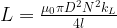
Spreadsheet Trap Calculator
The user will specify the resonant frequency, the winding spacing, and the dielectric properties. From equation [9] we can generate a set of coil geometries, 

Example output of the calculator is shown above. Most commonly, you would pick the frequency of the trap, knowing your wire size you can set the wire spacing for a close-wound coil, and then choose a geometry based on
Dealing with Dielectric Coating on Wires
Knight does not include any corrections for dielectric wire coating. However, his expression for coil capacitance does include 


I like to think of the capacitance of these coils coming from two sources. There is turn-to-turn capacitive coupling along the coil where the electric field is mostly in the dielectric between the turns. Then there is the “volume” electric field supported by the 

Measuring coil self-resonance
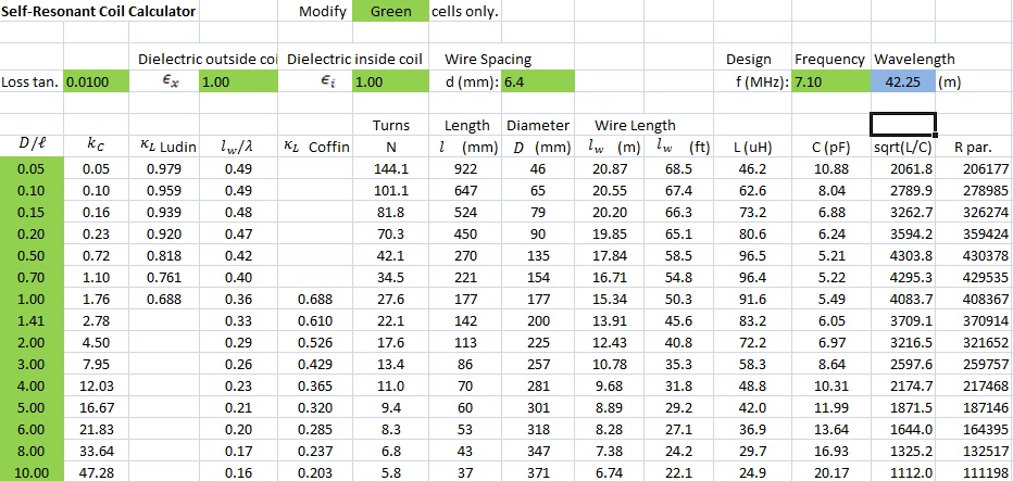
When I started making coils for antenna traps I did not have a good way to figure out how they performed other than to make the antenna and see how it did. I was able to get some information using a dip meter that confirmed I was going in the right direction. However, my purchase of the now ubiquitous NanoVNA has made quantitative measurements possible.
The difficulty with any measurement of the coil’s self resonant properties is that the capacitance involved can be small and you can be easily led astray by any test fixture capacitance and stray capacitance from the coil under test to ground. Suffice it to say I did my best to check for and eliminate these effects as much as possible. Using the NanoVNA’s S21 method seemed slightly better than the S11 method, but both methods had a bias for the “hot” output connection. Added capacitance or cable length on the hot side of the NanoVNA output was much more noticeable than if the wires were reversed such that added parasitics were on the ground side of the measurement. The NanoVNA was calibrated to account for the test fixture and test clips.
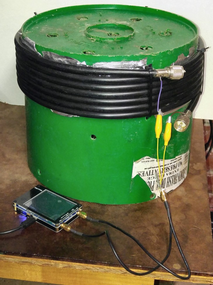
To begin with I measured several coils with various winding geometries and winding materials. Tested were close wound coils made from PCV-jacketed RG6, PE-insulated RG11, and THHN insulated #14 copper wire. With the NanoVNA it was a simple matter to determine the self resonant frequency and the low frequency inductance. The high frequency capacitance is a little more difficult because there can be higher harmonic resonances that make assignment less reliable, but combined with the low frequency inductance and the self-resonant frequency, an equivalent parallel capacitance can be calculated.
Since we know the coil geometry and its self-resonant frequency, we can use the spreadsheet calculator and see if we get agreement. The one unknown for the calculator is what to use for
| Coil | Description | 𝜖 jckt | 𝜖x best | coil Dia. (mm) | coil Len. (mm) | D/L | N turns | wire dia (mm) | wire loa (m) | f_sr (MHz) | L_lf 50kHz (uH) | C_hf (pF) | C_sr (pF) | L_calc (uH) | C_calc (pF) | Rmax |
|---|---|---|---|---|---|---|---|---|---|---|---|---|---|---|---|---|
| A | RG-11 on 10″ PE bucket | 2.3 | 1.9 | 281 | 70 | 4.01 | 6.9 | 10 | 6.1 | 9.15 | 19.8 | 19 | 15.5 | 19.8 | 15.3 | 37500 |
| B | RG-6 on 6″ PE flower pot | 4 | 2.35 | 156 | 43 | 3.63 | 6.2 | 6.9 | 3.2 | 18.9 | 7.6 | >3 | 9.2 | 7.6 | 9.3 | 15200 |
| C | RG-6 on 4.5″ PVC pipe form | 4 | 2.6 | 123 | 49 | 2.51 | 7.2 | 6.9 | 2.79 | 22.6 | 6.73 | 5.3 | 7.4 | 6.7 | 7.4 | 17300 |
| D | #14THHN on 4″ PVC form | 4 | 1.92 | 103 | 49 | 2.10 | 17 | 2.9 | 5.51 | 12.86 | 31.1 | 6 | 4.9 | 31 | 5 | 190000 |

The chart above shows a typical impedance sweep with a very clear resonance at about 19 MHz. At resonance, the coil has about 24 kΩ resistance with a modest bandwidth that would allow such a coil to be effectively used as a trap for a typical ham band. The measurements give good guidance for the value for
With the test coils on the bench there were a couple of other questions to explore. I want to understand how a hard rain would effect the performance of the coils as traps, so I soaked the coils with as much water as they could hang on to, simulating a rain-soaked operation, and measured them again. I also wanted to know what would happen if I wound the coils on a layer of aluminum foil to enhance the capacitance. A summary of the four measurements for each coil configuration is shown below.
| Coil | Description | 𝜖 jckt | f_sr Dry (MHz) | f_sr Wet (MHz) | 𝜖_xdry | 𝜖_xwet | f_wet / f_dry | f_sr Foil Dry (MHz) | f_sr Foil Wet (MHz) | Foil f_wet / f_dry | R_mx Dry (Ohms) | R_mx Wet (Ohms) | R_mx Foil Dry (Ohms) | R_mx Foil Wet (Ohms) | Q Dry | f_sr_Foil / f_sr_Nrml |
|---|---|---|---|---|---|---|---|---|---|---|---|---|---|---|---|---|
| A | PE-RG11 on PE bucket | 2.3 | 9.15 | 8.72 | 1.9 | 2.2 | 0.953 | 4.96 | 4.74 | 0.956 | 37500 | 37500 | 37300 | 18700 | 33 | 0.54 |
| B | PVC-RG6 on PE pot form | ~4 | 18.92 | 18.17 | 2.35 | 2.60 | 0.960 | 11.36 | 11.00 | 0.968 | 15200 | 15800 | 8090 | 7100 | 17 | 0.60 |
| C | PVC-RG6 on PVC pipe form | ~4 | 22.6 | 21.42 | 2.6 | 3.00 | 0.948 | 12.99 | 12.26 | 0.944 | 17350 | 13100 | 8500 | 7100 | 18 | 0.56 |
| D | #14THHN on PVC form | ~4 | 12.86 | 12.38 | 1.92 | 2.13 | 0.963 | 5.42 | 5.01 | 0.924 | 190000 | 91900 | 22900 | 14300 | 75 | 0.42 |
These measurements allow us to make a few observations. First, water wicked on the coils lowers the self resonant frequency about 5%. This could cause some de-tuning in the rain, but could probably be mitigated just by choosing the “dry” resonance a little on the high side. Which brings us to the second point; at resonance the real part of the complex impedance can be large, typical 20 kΩ or more. It is know than polyethylene has a much lower loss tangent than PVC insulation. That may be part of the reason why the large coil made from the PE-jacketed RG-11 had higher resonant impedance than the PVC-jacketed RG-6 coils. All of the coils tested have a large enough 5 kΩ bandwidth to cover the typical ham band.
Winding the turns over a sheet of aluminum foil generates substantially more self capacitance so that much shorter conductors with lower inductance can be used to achieve the same self-resonance. The Self-Resonant Coil Calculator spread sheet is not applicable in this case, so you would likely need to build and test anything you wished to make this way. For my test coils the self-resonant frequency was lowered between 42% and 60% when winding on top of the foil. The foil was gapped to allow the magnetic field in without driving currents in the foil. Nevertheless, the foil did slightly reduce the observed low frequency inductance of the coil by ~5% so there must be some image currents flowing in the foil.
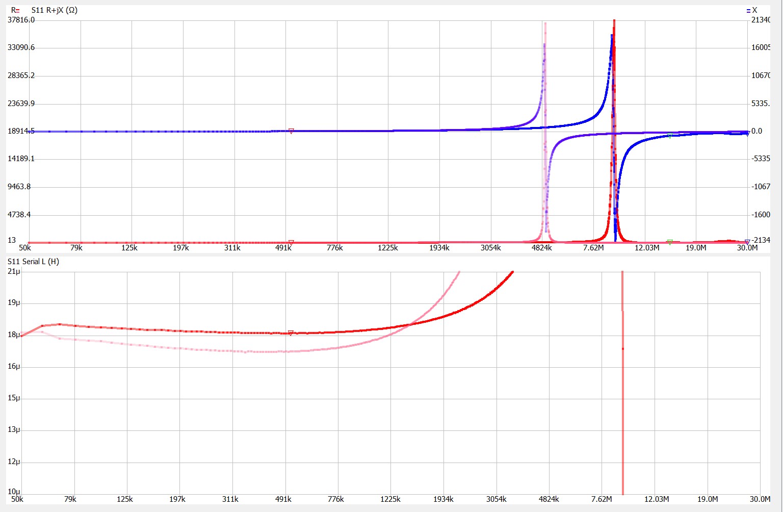
The lower NanoVNA plot above shows the equivalent series inductance as a function of frequency for a coil wound with (pink) and without (red) the aluminum foil layer on the form. For all of the tests, the low frequency inductance seems to reach a minimum somewhere around 500 kHz. The small drop in inductance between 50 kHz and 500 kHz could be the result of magnetic field being excluded from the bulk of the coax as the skin effect takes hold.
Self Resonant Traps

A resonant antenna trap is simply a parallel LC circuit that appears as a high impedance at the resonant frequency and thereby defines the electrical termination of a radiating element for the resonant frequency. When not at resonance, the trap will have a much lower impedance and will pass the RF beyond the trap. Self resonant coils made from the coaxial feed line allow the RF energy to be directly delivered to the antenna feed point while the self resonant coil defines the end of the radiating element and performs a function very similar to a feed line choke to keep RF energy off of the feedline back to the transmitter.
This type of trap is very robust. It has no discreet capacitor so nothing to blow up even at high power. With no break in the coax insulating jacket, the antenna trap does well in the weather.
I’ve built a few of these for a number of applications. Most often now I design for an extra half turn so that the coil naturally hangs from the cable. Using 
1 Knight, David W., An introduction to the art of Solenoid Inductance Calculation with emphasis on radio-frequency applications Local Copy
2 Knight, David W., The self-resonance and self-capacitance of solenoid coils: applicable theory, models and calculation methods. Local Copy

Nicely done Gary!
http://ham-radio.com/k6sti/wbc.htm
http://ham-radio.com/k6sti/coil.htm