
Top Band, as 160 meters is called, presents a a challenge because the long wavelength leads to large antennas. One can always play tricks with loading to be able to use a physically shorter length of wire. There are many articles on compact 160 m antennas, but this is not one of them. Rather, I’m going to consider a full size half-wave antenna that lends itself to being pulled into trees and resonates on other bands as well as 160 meters. If we are going to do the work to get a long wire up in the trees, it should be good for at least a couple more bands as well 160 m.
First attempt – a 160m / 20m vertical antenna

My first 160 m antenna is a modification of a 20 meter collinear vertical that I was experimenting with. A diagram is shown in the figure on the right. For the 20 meter collinear, there is an upper half-wave section, a phasing inductor, and the lower half-wave section that includes the feed point from the 75 ohm coax. A 20 meter trap inductor wound from the coax defines the end of the lower half-wave section. Lets just say that this collinear (and its improved new cousin) has worked well enough to keep its position pulled up in the tree. With such a tall wire, going up more than 120 feet, it seemed like a good idea to use it also as a 160m vertical. To accomplish this, I wound the coax feed on a large ferrite choke just before it went down the chimney feed-through into the shack. Just above the ferrite choke I made a good connection to the coax outer conductor to which I planned to attach a pair of elevated radials. Finding a place to run both radials proved difficult, so I ended up just using a single radial counterpoise.

This arrangement got me on the air on 160 m. You can see the 4NEC2 run for this arrangement in the figure. The single elevated radial makes the pattern asymmetric. In practice, this turned out to be a very good antenna to reach stations a few hundred miles north of me, the direction the radial was pointing. I have been very frustrated when trying to be heard to the south. The overall gain is also nothing to be proud of. I believe what is going on here is that the low radial is coupling fairly well to the ground below it and sucking up much of the power to ground losses. In retrospect, I’m sure the common mode choke for this antenna was also inadequate, as we will discuss below.
With many model runs, and experience with a few antennas that have made it into the air, if there is a rule of thumb for HF antennas it is to get as much wire as high up as possible. Applying this lesson to the 160 m antenna suggests the inverted L has the potential to work better, with a top horizontal section that will act somewhat as a capacitive “hat”, and some shorter elevated radials also acting capacitively.
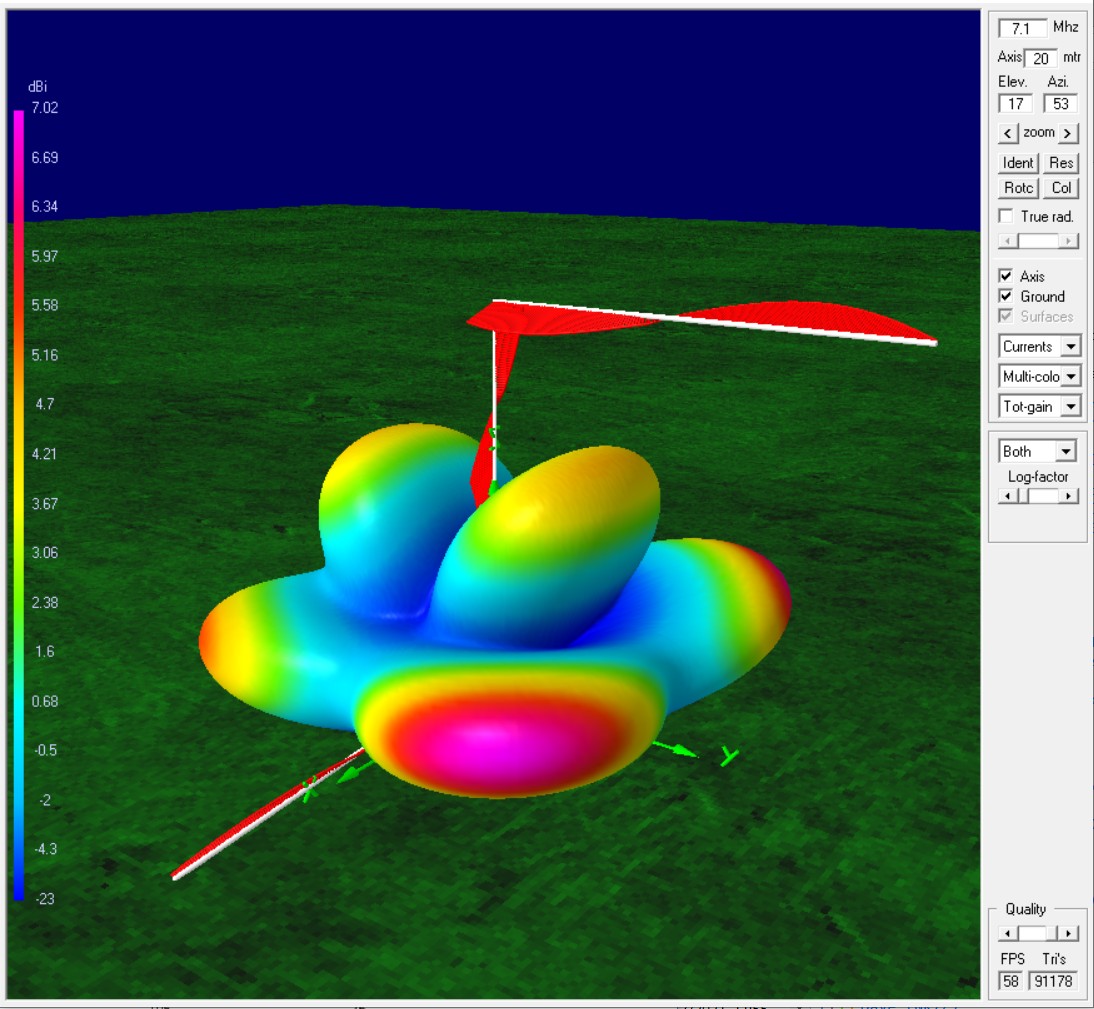
A 160m / 80m / 40m multiband inverted L
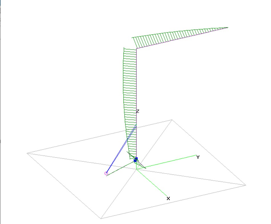
My approach for feeding a vertical wire antennas is to use 75Ω coax feed line directly to the main vertical wire. The outside of the cable shield becomes the lower radiating sections of the antenna. The end of the radiating coax section is delimited by a ferrite feed-line choke for the low bands or an air-core trap for high bands. I have tall trees so this antenna is up close to 40 m (131 ft.) high. The lower radials and feed line remains elevated at about 3 m (10 ft.).
It seems a shame not to take advantage of a very high-top wire for a couple more bands. Least served by my other antennas are the 40m and 80m bands, so I included a coil “trap” for 40m in the design options options for this big inverted L. The list of major tuning / design parameters include the following:
- Length overall of radials, vertical section, and top horizontal section.
- Height of the feed point where coax ends and wire begins.
- Fractional point where the wire folds horizontal at the top.
- The distance from the feed point to the 40 m trap.
- The coil parameters for this trap coil.
- The length of the 75Ω mis-matched feed line.
The design process was laborious with a lot of trial and error. Despite all of the possible parameter variations, it seemed almost impossible to get good resonances on the three desired bands, but with persistence a solution gradually emerged. The model diagram and a typical SWR sweep are shown below.

I still wanted a lower SWR on 80 m, but this seemed like a worthy antenna to put into the trees. A little over a year ago, I cut the wires and cable, wound the chokes, and pulled this into the trees. Naturally, when I pulled it up, it was not exactly tuned and I needed to trim the horizontal wire and the two elevated radials to get it too work. At the time, my antenna analysis equipment consisted of a return loss bridge and a white noise RF source. Below is the return loss frequency plot – nothing pretty!

Despite the rather poor equipment, I was able to see the 160m and 40m peaks move about as I trimmed either the radials for 160, or the horizontal wire for 40. Changing the radials had little effect on the 40m band because of the 40m air core trap coil located on the feed line just above the connection to the radials. The 80m band was not so great, but so it goes. Nevertheless, I found that the new inverted L was working substantially better on 160m than the version piggy backed to the vertical collinear.
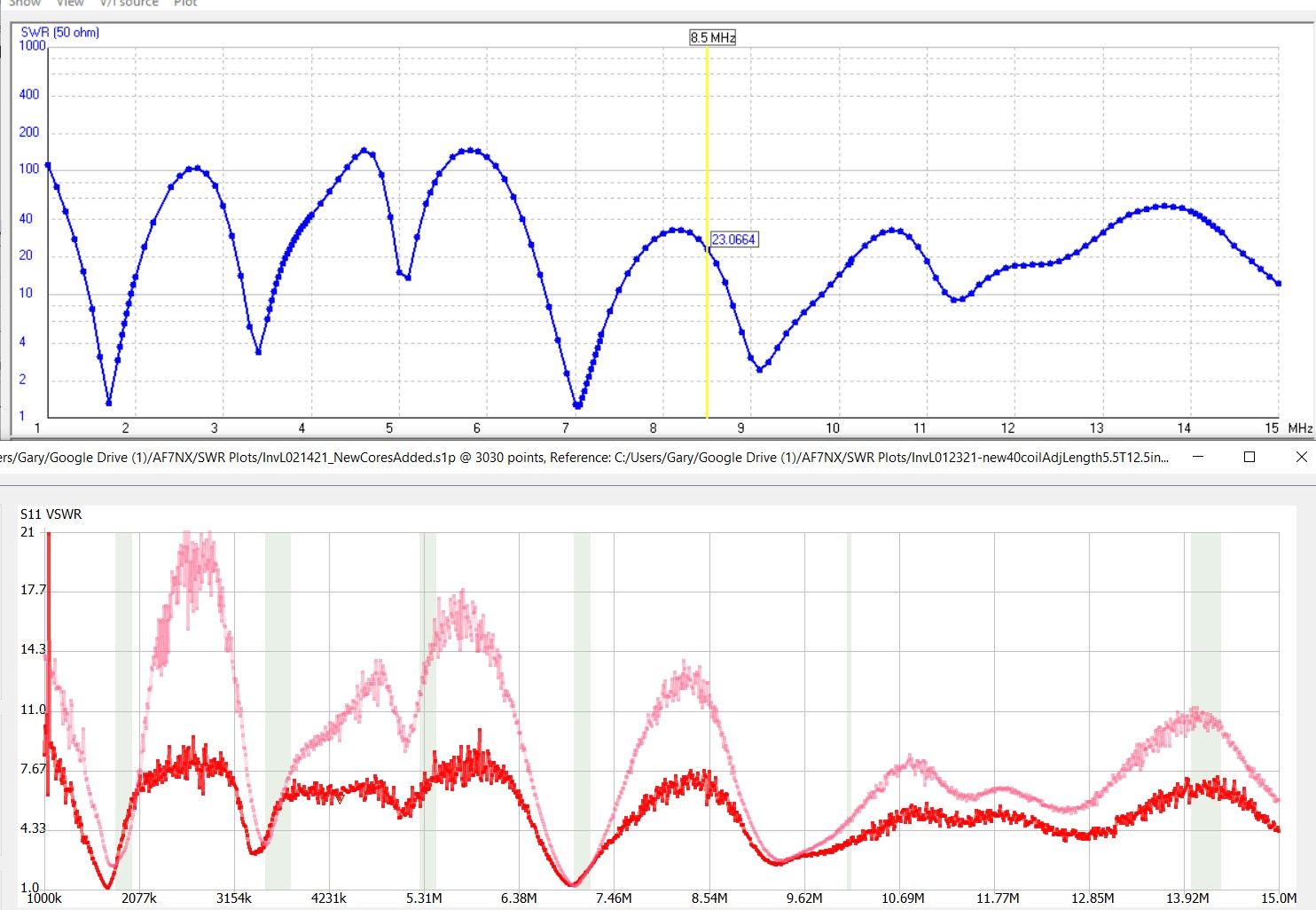
When I got my new NanoVNA analyzer, I ran a plot on the antenna.

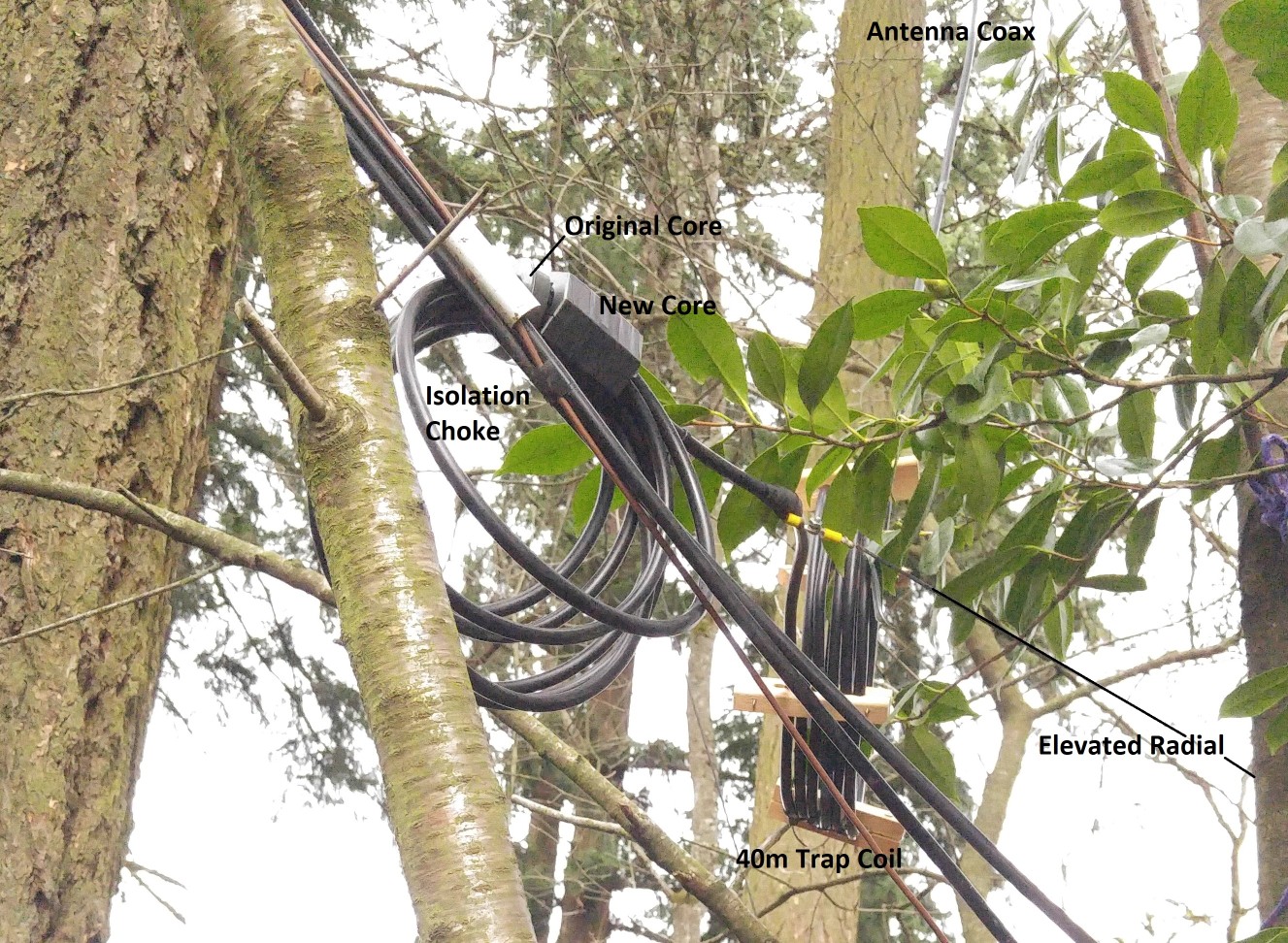
You can see that the NanoVNA and the previous measure by the return loss bridge more or less agree with each other. And you can see that this plot doesn’t look very much at all like the original model run! Although I was getting reasonable performance on 160 and 40, the 80 meter band was not doing very well at all. My nagging concern was that I had poorly handled/modeled the actual choke coils that I used. For the 40m trap coil I had made and “ugly balun” consisting of a few turns of the RG11 tied together with cable ties with little control of the actual stray capacitance. The isolation choke was 8 turns of the RG11 feed line through a single FT240-31 ferrite core. The easiest thing I could do was to snip the cable ties holding the ugly balun together and see what happened, so that is what I did and boy did that change things. See the plot below.

At this point I realized that I needed to have better control over the trap coil. I fashioned some wire spacers and rewound the coil using the spacers to generate a coil that was amenable to calculation of both L and C using my coil calculation tool. I also had been measuring various ferrite choke coils with the NanoVNA, and could assign more realistic values into the model for the choke properties.
After adjusting the coil properties in the NEC model and tweaking a few parameters a little to make the bands line up, I was able to get much better agreement between the model run and the NanoVNA SWR plot. See below.

At this point I had confidence that the model and reality were reflecting one another. However, what the model was saying was troubling. I had included the measured values for the isolation choke – 145µH, about 30 pF parallel capacitance, and an equivalent parallel resistance of about 3.0 kΩ. Ferrites have core losses and the way that appears when making self resonant choke measurements is in the form of a finite parallel resistor. This turned out to be a significant loss mechanism. The NEC model suggested that ~60% of the RF energy was being used to heat the core!
Alarmed by the model results, I fastened a small temperature probe to the surface of the ferrite core and turned on the transmitter with 50W at 1.8 MHz. To my chagrin, the temperature screamed up on the surface of the core. Quite a bit of that 50W was turning into heat in the ferrite. After five minutes, the core temperature had increased 72 °C. Calculating the specific heat and mass of the cores, easily 40% of the energy was going to heating. This is more or less in line with the NEC code using the measured choke parameters.
The solution was obvious — I needed way more ferrite core material to substantially increase the inductance. With the antenna already in place, I opted for one of the large split ferrite cores made of mix 31 material that are available. When I received the core, I built a test choke with 8 turns of RG11 and measured the performance. The results: 690 µH, ~ 28 pF, 14.0kΩ. I estimated conservatively that adding the new core to the same coil with the existing torroid would result in about 790 µH total inductance and perhaps 15.0 kΩ parallel resistance, so I used these values for the next model runs.
Good things happened with the new ferrite in place. SWR on the low bands dropped and the model showed that the electrical efficiency increase to about 80% rather than 40 % on the 160m band. Efficiency is >95% on 80m and even better on 40m with the new ferrite according to the model. The bands needed another alignment adjustment with the big ferrite installed. The model showed good results just removing the shorter of the two elevated radials. Armed with wire cutters, that was a quick change which improved things a lot. A few small adjustments to the 40m coil brought us to the alignment shown below.
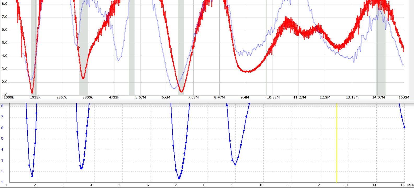
The agreement between the model and the measured results are really quite impressive. So is the improvement in the tuning on the 80 m band compared to where it was before I did this exercise. On top of all that, I probably have 50% more power actually turning into 160m radiation now that I have a sufficient isolation choke coil.
Performance
The radiation patterns for the three bands are shown below.


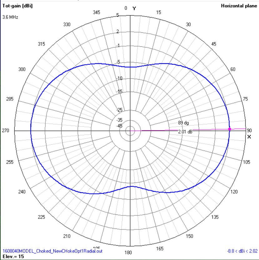
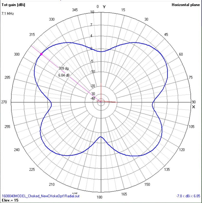
The lower set of charts show the horizontal pattern at 15 degrees of elevation. These are reasonably good patterns for these low bands. The nulls are not too deep on 40 and 80 because there is energy coming from the vertical wire section tends to be axisymmetric, as well as energy from the horizontals sections of the wire. In retrospect, I wish that the wire was aimed North rather than South as it is installed. The stronger 40m lobes would be aimed at good targets in the Europe and Asia instead of Australia.
The antenna is exceptionally effective for domestic stations. Especially at higher elevation angles, the 80m lobe covers much of the USA. The big wire generates big signals. It is common to need to attenuate received signals. AM broadcast band stations nearby generate signal levels on the wire measured in volts. I commonly employ an AM broadcast band filter when listening on this antenna on the RX antenna connector of the receiver. This is especially important when listening with wide band receivers such as SDR’s that deliver the entire antenna bandwidth to the detector.
On 160 meters, for regional rag-chews up and down the west coast, I can usually be heard well with 100 W, often better than stations running more power. It is still a challenge to do 160m DX with 100 W in a noisy urban environment. Time will tell if the recent improvements bare fruit.
Recipe and Model
In the optimization process I discovered a few general principles that allowed for the three bands I wanted. The antenna is directly fed with 75Ω RG11 cable. To make use of the odd-quarter wavelength anti-reflection property of a mismatched cable, I chose the overall feed line length to be 54 meters electrical length, which is about 148 ft. of RG11 with 84% velocity factor. Slightly longer length will work better on 80m, a little shorter will work a little better on 40 and 160, but this length is a good compromise and fits with the length of line I needed to reach my tree and to wind all of the coils that need to be on the feed line. This length cannot be changed arbitrarily without reoptimizing the model.
The “40 meter trap” ended up with about a 12 MHz self-resonance – so not really a trap. The coil along with the elevated radial manages to define the end termination for 40m. The coil ended up about 4.5 turns of RG11 single layer wound, about 12″ in diameter, with estimated parameters 9.6 µH and 18.5 pF. The picture of the chokes above show the radial wire pick-off point between the “40m coil” and the ferrite isolation common mode choke. To make the radial attachment, the jacket was removed for an inch or so, the aluminum braid was cleaned and spread with CuAl electrical joint paste. Then solid #14 CU wire was wrapped tightly the entire length of the exposed braid, a connector was put in place on the paired copper wire ends and the entire region was taped up to keep the joint water proof.
Once past the coils, the coax feed line continues upward about 35 ft. to where the center conductor is attached to the long antenna wire. The braid was neatly folded back to avoid sharp edges and the joint area made waterproof with silicon tape. The #14 THHN antenna wire continues on up to the top pull point of the antenna about another 65 ft. above the coax connection. It then threads its way through some branches to the second high pull point with another ~114 ft. of wire. Total wire length according to the model is about 180 ft. from the connection to the coax to the very end of the horizontal pull.
Much of the fine tuning of this antenna can be accomplished near ground level. The length of the elevated radials are an easy-to-adjust parameter, and the size of the “40 m trap coil” can have a dramatic influence on exactly where the resonances place themselves. I fashioned at looped pull-up line for the very end of the wire so that I could easily pull the wire end up/down to trim the overall length.
For those wishing to build something similar, the model is available from the link below.
