I finally put up an End Fed Half Wave (EFHW) wire. I wanted a “standard” 80 meter wire as a comparison antenna for various other projects and the time and place was right. Besides, I had a new EFHW transformer to test out. It all started when working on the common mode isolation for an experimental “QuadPod” antenna where I was using some small binocular BN43-202 cores to see if I could improve the isolation on the four feed-lines with individual 1:1 voltage transformers. The method seemed to work quite well with RX, and since I had done the work, I thought maybe I could do a little low power TX as well. As anticipated, the small cores did get too warm after a couple of cycles of 100W FT8 transmissions, but the proof of principle suggested that I just needed a bit larger core. A search revealed that the “next size up” core is a BN43-3312 binocular core, so I ordered a few. As 1:1 transformers for the QuadPod, they proved to allow indefinite 100W transmission. In the back of my mind was the work I had done previously on EFHW transformers and a gut feeling that these cores would be perfect for that.
Using Binocular Ferrite Cores
If you take a look at just about any modest power RF amplifier, you are bound to see the RF transformers near the power devices. They are almost universally some sort of binocular ferrite cored transformer. The pros know that there is a good reason to use the dual aperture binocular core. The inductance per turn is maximized by having all that ferrite right next to the wire and hence leakage inductance is low. If the core is destine to get warm, it is simple to get the heat out from the exposed flat core surfaces. Why not use a binocular core for the voltage mode EFHW antenna transformer?
The BN-43-3312 core is only 19 grams, compared to the FT240-43 which is a hefty 123 grams. However a single turn on the BN-43-3312 core provides about 7 uH inductance compared to only about 1 uH for the FT240-43 core, traditionally used for EFHW transformers. My scaling experiments showed that overall efficiency and low frequency performance was better with relatively more primary inductance whereas high frequency performance was better with fewer turns and hence less primary inductance. For the BN-43-3312, the questions is whether one or two turns on the primary. I opted for two turns to emphasize low band performance and efficiency.


Winding 14:2 transformer on BN43-3312 core.
It is possible to carefully wind a single layer of 14 turns inside the binocular holes using #28 magnet wire. This way turn-to-turn voltage is graded uniformly across the winding and there is less chance of voltage breakdown of the enamel insulation. Rather than winding as a customary auto-transformer, I opted to keep the primary and secondary windings separate. This way you can use a deliberate counterpoise rather than the feed-line coax. I placed short plastic straws inside the holes. This kept the secondary pressed neatly against the core and added a little distance and insulation for the primary, two turns through the center of the straws.

I ran the same core loss measurement that I had done with the FT240 cores previously. The plot shows the binocular cores follow the same loss scaling with primary inductance as do the big toroids. Above about 18 MHz all of the type 43 cores start showing more loss with increasing primary inductance. This is consistent with core material displaying a large imaginary component of the complex permeability above 10 MHz. The graph above shows the trade off of bandwidth and efficiency. For 10 MHz and below, the two turn primary results in about half as much loss as the single turn primary. For working only on the lower bands you can run more power without having the core heat up. However if you wish to work the 12 and 10 meter bands, then the single turn primary is workable whereas the losses with the 2 turn primary become prohibitive for those frequencies.
This all looks very good, but begged the question about how to get good performance for the 10 meter band. There are ferrites better for higher frequencies, so I made a search for modest size binocular cores with such mixes. The standard core I found was a BN61-002, a slightly larger binocular core (49 grams) of type 61 material. I purchased a couple of them and made similar turns number tests with the type 61 binocular cores.

Note the change of scales on the chart above. the transmission losses with the type 61 core hover around 0.2-0.3 dB over almost the entire HF spectrum, somewhat better than the 14:2 type 43 binocular core. Surprisingly, for the type 61 material the losses were relatively independent of primary turns, unlike the type 43 material. In fact the single turn primary had the lowest losses everywhere and is potentially useful up through the 6 meter band. More turns just degraded the high frequency performance without offering any advantage at lower frequencies with the type 61 material. Nevertheless, with the BN61-002 core I found the 14:2 winding worked best; the 7:1 winding had trouble driving the 80 meter band.
Consider the significant improvement in efficiency compared to the big FT240-43 cores. The FT240-43 with a 14:2 winding is only about 75% efficient through the HF region, whereas a 14:2 winding on the much smaller BN61-002 core is about 93% efficient, one quarter the heat going into the binocular core compared to the big toriod. Power handling for the type 61 material is further enhanced because the curie point for type 61 material is >300 °C compared to 150 °C for type 43.
Constructing the Transformer


Packaged transformer with the BN61-002 core and 14:2 winding glued to the lid.
Time to build something. I found a small plastic box with a metal lid which allowed for low capacitance terminals for the antenna wires, simple BNC connector mounting, and heat dissipation for the transformer which was glued to the metal lid. The entire assembly weighed in at about 100 grams with the bigger BN61-002 core, easily light enough to fly on the antenna and counterpoise wires. A ten foot counterpoise to the isolated low-side terminal seems to work well and I did not attempt to adjust the counterpoise length in the tuning process I describe next. Modeling has shown that about a 10 ft. long counterpoise is a good match for the 49:1 transformer and that changing the length of the counterpoise has much less effect on setting a resonance frequency that does changing the length of the main wire.


The photo above shows the installed antenna feed section with counterpoise, transformer box, and main wire with a compensation coil. The photo on the right shows a simple and effective “quick adjust” coil form for the compensation coils riding on the main wire. The slotted locking holes securely hold the coil on the wire and make it very easy to change the number of turns or its position.
Matching to the Wire
An “80 meter wire” is actually about 137 ft. long, roughly the half wavelength of an 80 meter electromagnetic wave. In practice, an “80 meter wire” is trimmed with the aid of an antenna analyzer, so I have no idea exactly how long it really is, which depends somewhat on the insulation on the wire and how far it is off the ground. You can always trim the wire to the length you want to make the resonances line up with a ham band you want to use.

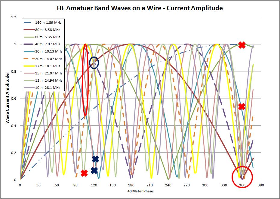
Getting the wire length “right” so that all the bands line up can be frustrating with multi-band 80 meter wires. If the higher harmonics are about right, the wire will “look long” to the fundamental because of capacitive end effects. The green curve above show the resonances on the wire I trimmed to be “a little long” for 80 meters and “a little short” for 20 meters and up. You could make this work with an antenna tuner, but I want to do better. The trick is to use small coils of antenna wire, strategically located on the wire, to modify the resonances. The easiest one to understand is the coil I used to reduce the gap between the 80 meter and 20 meter resonances. I chose to place this coil of wire about 15 ft. from the end of the wire. The currents on the wire at that point are about twice as large for the 1st, 2nd, 3rd, and 4th harmonics (40, 30, 20 and 17 meter bands) than for the fundamental resonance (80 meter band). When there is substantial current on the wire, the coil will make the electrical length of the wire “look longer” because of mutual coupling between the turns of the coil. For the upper bands, 15, 12, and 10 meters, the location 15 feet along the wire is near their first harmonic null, so there will be less effect lengthening the wire for these bands. If there is little or no current where the coil is located, the effect of the coil will be mostly capacitive, somewhat bypassing the coil and potentially shortening the electrical length of the antenna. You can see the results of a 10-Turn 2″ diameter coil located 15 ft. from the end of the wire in the blue curve above. Notice that the blue curve is just a little bit better for the 80 meter band, with the SWR minimum right at the lower band edge. The 20 meter resonance has moved from just above the 20m band to just below the band. We shortened the wire for 80 meters while at the same time lengthened the wire for 20 meters by just coiling up some of the antenna wire at the right spot. If you look at how much the bands moved, it seems that the “lengthening” effect where the current is strong is the biggest factor, but we also see that the wire did “shorten” for the 80 meter band.
I also made a small coil at the feed end of the wire, now looking to tackle the upper bands so it is closer to the end of the wire (feed point) where the upper band currents are higher. A coil on this end can further tune the wire in a similar fashion, and can also help compensate for excess capacitance in the transformer. I found that an 8-turn coil 19 inches from the transformer gave the best results, shown in the red curve below, compared to the green curve which was the original wire without coiling up bits of it.

This is largely an empirical process for which you can spend as much time as you are willing to give to the problem. I was up and down the ladder 50 times before I got results I consider satisfactory. All of the bands except 10 meters are under SWR 2, even the hard-to-tune 30 meter band. This is a good starting recipe for any 80 meter multi-band wire.
With five variables, wire length, the two coils location and number of turns, the optimization process is a bit tedious but not totally unpredictable. When I started this process, I didn’t think there was any hope for the 30 meter band. Seeing the results now, I might try harder for it by moving the far-end coil to the location of the 30 meter current maximum – closer to 20 feet from the end of the wire rather than 15 feet. That might also help 17 meters… The point is that there is method to the madness. But I had to stop somewhere so I will leave that project for another day.
The EFHW wire is popular because it is relatively easy to devise a mounting arrangement when you might not have the space or facility to mount the wire straight out. If it is mounted with a fold to the wire, chances are that the resonance points will move a little. My recipe will probably not work, but the basic method for adjusting the resonance points of the various bands with small coils on the wire should be applicable for any multi-band wire antenna.
Power Handling
To test the power handling capability I made some extended FT8 transmissions while measuring the ferrite core temperature, transmitting long enough to reach thermal equilibrium. The measured temperature rise was ~7.5 °C on 80 meters, ~5.5 °C on 20 meters and ~10 °C on 10 meters when transmitting FT8 signals at 100 Watts using the BN61-002 core. The good news here is that the temperature rise is modest enough that the core could easily tolerate ten times more power. This transformer should be good to kilowatt power levels without overheating.
Discussion
On initial tests I would get a little RF back in the shack on some bands. This manifests as a frozen computer mouse during the TX intervals in my shack. The usual culprit is the feed-line. The separate primary and secondary windings reduce this problem considerably compared to the old auto-transformer design where the cable shield is forced to take some counterpoise RF current. Nevertheless, running the feed line through a ferrite with a few turns completely eliminated the issue. This choke was well down the feed line ~ 20 ft. from the transformer. Common mode current should be close to zero right at the transformer because of the isolated windings.
I’m not aware of any other EFHW design that offers such a light-weight, efficient, and easy to build EFHW 49:1 transformer that can take any power you wish to give it. If you care about a few grams of weight you can use the BN43-3312 core. If you want good efficiency on 10 meters, then use the BN61-002 core. It is an easy recipe. I don’t want to see any more copycat transformers with big FT240 cores used for these things any more. Get smarter, smaller, lighter, and better! Put together a simple system that will make those EFHW skeptics eat their words! Just because it is easy doesn’t mean it can’t work well. Multi-band wires are always a bit of a compromise, but what is not to like with an eight-band antenna you can use effectively without an antenna tuner.


Hi
Love the binocular core. I have some questions
1. How would this antenna fair (or shorter one for 40-10m) in portable use where site and height differ each time?
2. Curious- why aversion to ATU? I use small L-match w 58 ft EFRW and 9:1 coupler. How low insertion loss and multiband use.
3. How could I use the binocular core for a compact 1:1 balun (or common mide choke)?
Love your in-depth articles.
Best 73, Scott VA7SNJ
Scott,
The transformer would work fine on the shorter wire — you might want the 7:1 turn ratio which works a little better on 10m and could potentially get you to 6m. You would have to experiment a bit to find the best place for the coils on the wire. 40 meters is going to “look long” compared to the rest. The 40m wire will not have the WARC bands on it (the beauty of the 80m wire). Once you’ve found the right spot for the coils on a straight wire, they will be pretty close even if the wire is deployed with a kink — and you can roll them one way or another and get it to work.
My aversion to an ATU is that I don’t have one:) If you can get the basic wire under SWR ~3-4 you are not loosing much when you tune it with the ATU.
The Binoc cores are especially valuable when making voltage transformers, where leakage inductance matter a lot. For the mid feed CMC, just bring with you any ferrite core that you can get the connector on your feed cable through the hole and place a few turns. ( avoids connectors which is a big deal in my book) that is the main advantage of the FT240 cores, you can fit the connector through the hole! For light weight operation you could use a smaller core on your feed line and connectorize it after you put the turns on the core.
One to pass along!
73,
Ken
w0yre
One to pass along!
73
Ken
W∅YRE
Some thoughts – core losses are dependent on a few parameters – gauss level, temperature, frequency, etc. Going from 2 turns to 1 turn raises the gauss level and presumably increases the core losses. At the same time, going from 2 turns to 1 turn lowers the wire losses. The skin effect pushes the current to near the surface of the wire and proximity effect can push the current that is already near the surface to one side of the wire, increasing the AC resistance even more. Both skin effect losses and core losses increase with frequency – except that the gauss level goes down with increasing frequency – less volt-seconds. Here’s another interesting characteristic – the presence of the core does not affect the leakage inductance. This last one I had to demonstrate in the lab to the young engineers who challenged it. I’m not surprised the graphs you measure are hard to understand why they are the way they are! Another measurement to add to your arsenal is self resonance. The closer you are to the hopefully relatively high self resonance frequency you are, the harder it is to transfer energy.
It would be interesting to rewind the secondary with a multiple strand twisted rope of smaller gauge wire. Or with Litz wire.
My background is switching power supply transformer and inductor design. I am still humbled by the differences between power transformers running at 500kHz vs RF transformers running in the megahertz range.
73 Dave kx3dx
Hi Dave, Thanks for the thoughtful comment.
>Going from 2 turns to 1 turn raises the gauss level and presumably increases the core losses.
Yes, I think of this effect as pouring current in the resistive part of the complex permeability — but yes, this is what is observed.
>Both skin effect losses and core losses increase with frequency – except that the gauss level goes down with increasing frequency – less volt-seconds.
Maybe, but in general the resistive part of the complex permeability increases with increasing frequency. My intuitive model of this is the fact the the magnetic domains that have to shift around during magnetization actually have a bit of inertia, introducing a phase shift as the frequency increases. Is that true or just my overactive imagination?
>the presence of the core does not affect the leakage inductance.
Hmmm, I think of leakage inductance as resulting from flux in one winding that is not linked with the other winding. Hi mu cores change the flux distribution in their neighborhood, tending to concentrate the flux in the low reluctance path of the core. Now, there will always be a little flux around each wire that is not in the core – and that will be roughly the same regardless of the core, and hence I guess would be approximatelyt independent of it, but the ratio of primary inductance to leakage inductance will be much larger with a core.
> The skin effect pushes the current to near the surface of the wire …
Yes, skin effect is certainly an issue, one reason I never understood the desire to use super big wire on these things. The crossectional are where there is conduction goes as r rather than with the area going as r^2, so indeed multiple small wires are better than one big wire of the same cross-section. In my case, I calculated the effective resistance of the wire at 30Mhz (about 2 ohms) and compared it to the driven impedance (about 2500 ohms) and considered that to be OK.
Cheers,
Gary
From Dave continuing this discussion…
Yes, it’s counterintuitive that leakage is not dependent on the core. All my magnetics were manufactured at outside vendors where we would specify to check leakage on a wound coil form without cores before impregnation to confirm the placement of the windings were compliant to the build documentation. These were mainly E-E and U-I coil forms with multiple windings used in switching power supply transformers. Leakage/coupling is purely geometry/placement between windings as I recall? I don’t have access anymore to my MathCad files so this is from memory. I recently asked AI (not that I always believe AI) if this is applicable to toroids. It replied affirmative. Testing without cores means the frequency selected need to be high enough so that the inductance meter can drive the low impedance of a winding without the cores properly.
Wire losses – I agree the AC resistance of the wire due to skin and proximity affects are minimal when compared to high impedance on the secondary winding but maybe at high powers the primary 2 or 3 turns might get warm at high powers. Keep in mind the nasty positive temperature coefficient of the resistance of copper.
As far as higher power is concerned – the secondary voltage will get pretty high – adjacent turn to turn voltage may be well within the magnet wires insulation capability but end to end of the secondary winding may not be. There are single, double and triple build polyamide insulation wire that all have different voltage ratings. Also note that cleaning certain types of magnet wires with alcohol or other solvents can cause crazing (cracks) of the magnet wire insulation if the coil isn’t annealed (heated) after winding and before cleaning. I see many pictures of failed endfed transformers and I wonder which “gotcha” caused the failure. In the BN style transformer, insulation breakdown between wires could be an issue at high powers.
Core losses – in power material used in switching power supplies, the material manufactures give us a nice graphs for determining core losses – you need to know gauss level, frequency, temperature and volume of the core. I’m not sure these same short cuts are provided for RF and EMI materials – I haven’t looked.
I’m still learning the difference between power magnetics and RF magnetics. I’ve wound a few end fed transformers and I like the BN idea because for portable backpacking, it has quite a weight advantage. I don’t worry too much about 1 to 2 dB of loss. Good placement (height, compass orientation, etc.) makes more dB difference then a few dB of matching and coax loss. One of my favorite antennas is a 20m half wave end fed antenna that I can also use on 10m. I don’t go for the all band in one antenna thing – I also have a half wave 40 meter end fed at home – again, two bands, 40 and 20 is all I expect out of it and optimizing a transformer for that limit frequency range is easier. It works very well at a height of 45 feet on both ends, away from other trees or structures in an open field, with the coax at perfect right angle to the radiating wire, all the way down to the ground. Details matter.
73 Dave
Thanks again for your comments Dave,
One thing I noticed when doing my scaling experiments was that low frequency materials used for power magnetics behave quite differently than RF materials. All materials have losses that increase with frequency, but the scaling for high permeability MnZn ferrites suitable for power switching applications is much stronger (larger exponent) than for RF ferrites, especially the NiZn varieties.
Also, my scaling experiments showed that the total losses are quite independent of core volume. If you want lower losses, then you need more primary inductance. That usually means more total turns, which usually makes trouble for the top end.
As you point out, voltage hold off should not be taken for granted. I think grading the winding using a neat tight single layer coil is the best way; then adding insulation between the primary and secondary.
Good luck with your builds!
Cheers,
Gary