After a few months of pondering how to build a simple pull-up vertical collinear antenna, I think I’ve finally got it! The motivation for such a design is the fact that I have tall trees for a support and can actually pull such an antenna up into the trees to 100 ft. or even higher. We all know that higher is better – and that is true with vertical antennas as well as horizontal dipoles.
The collinear design is simply two in-phase half-wave dipoles place end to end with a separation between the ends. This is simple enough in principle, but somehow you must feed each of the two half-wave structures with the proper phase while not having your feed lines short out the fields you are trying to produce. My first attempts fed the lower dipole via a co-ax line and I then tried to build a resonant structure that would send the wave up the wire to the top part of the antenna, phased with an inductor or a zig-zag delay line phase structure between the two halves. Unfortunately, these designs were difficult to model convincingly. The biggest problem is with the inductor, which is doing double duty as defining the ends of the radiating half-wave sections and as the phasing element. There still may be hope for these all-wire designs, but for now it was time to move on to something more theoretically tractable.
I decided to try for a design that deliberately fed the upper section with a coaxial feed line. The design I ended up with is elegant, robust to small dimensional changes, and offers very good theoretical performance. The figure below illustrates the design process (click to enlarge).
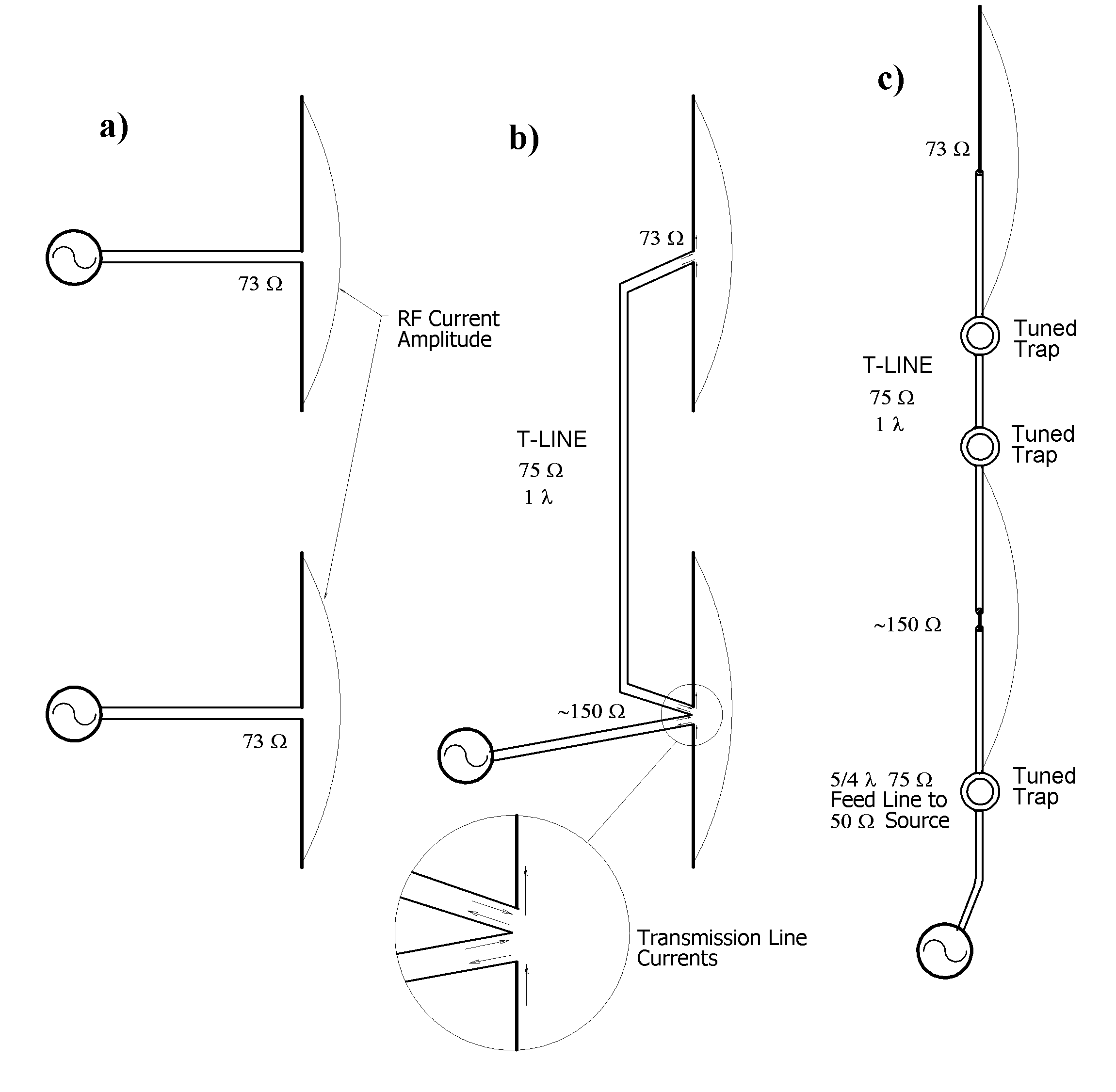
The collinear antenna gets its increased gain by doubling the number of half-wave active elements, effectively increasing the antenna aperture. For this to work, the two elements must work together in phase. One way to achieve this result is shown in b) above, where one element of the antenna is driven “in series” with the transmission line one wavelength long that then drives the second dipole section. Free space dipoles have a driving impedance of about 73 Ω when fed on center. If we use 75Ω line between the two elements, then the impedance and phase at the two ends of that line will look identical. The driving source will see the 73Ω impedance of the lower element in series with the transmission line impedance of 75Ω (which is well terminated by the 73Ω load of the upper dipole), hence about 150Ω is presented as the load to the driving transmission line.
Transmission lines have the property that the currents are balanced along the line. A coaxial line illustrate this best. The current coming out of the center conductor is balanced by an equal and opposite current traveling on the inside of the outer conductor. All of the fields, both electric and magnetic, are confined in the dielectric between the center conductor and the outer conductor of the cable. This happens because the mutual inductance of the two conductors of the transmission line is large and because, for RF frequencies, the skin effect prevents the fields from leaking out of the shielding conductor. If you look at the inset in the diagram above, you can see how the balance currents in the feed transmission line must be identical as the currents injected into the transmission line to the top section, and also identical to the current magnitude on the lower half-wave dipole.
The practical implementation, c) above, uses the outside of the coax shield as the dipole half-wave elements. The feed current, coming up the coax from the source encounters the break in the coax shield at the feed point for the lower dipole. For the currents to be continuous at this juncture, the current on the inside of the coax shield must turn the corner and go back down the outside of the shield. The center conductor current continues into the center conductor of the transmission line to the top dipole, and must be balanced by the current on the inside of this coax’s shield. But for the current to be continuous at the break, again we are forced to have a current in the outside of this transmission line’s shield as it turns the corner into the cable.
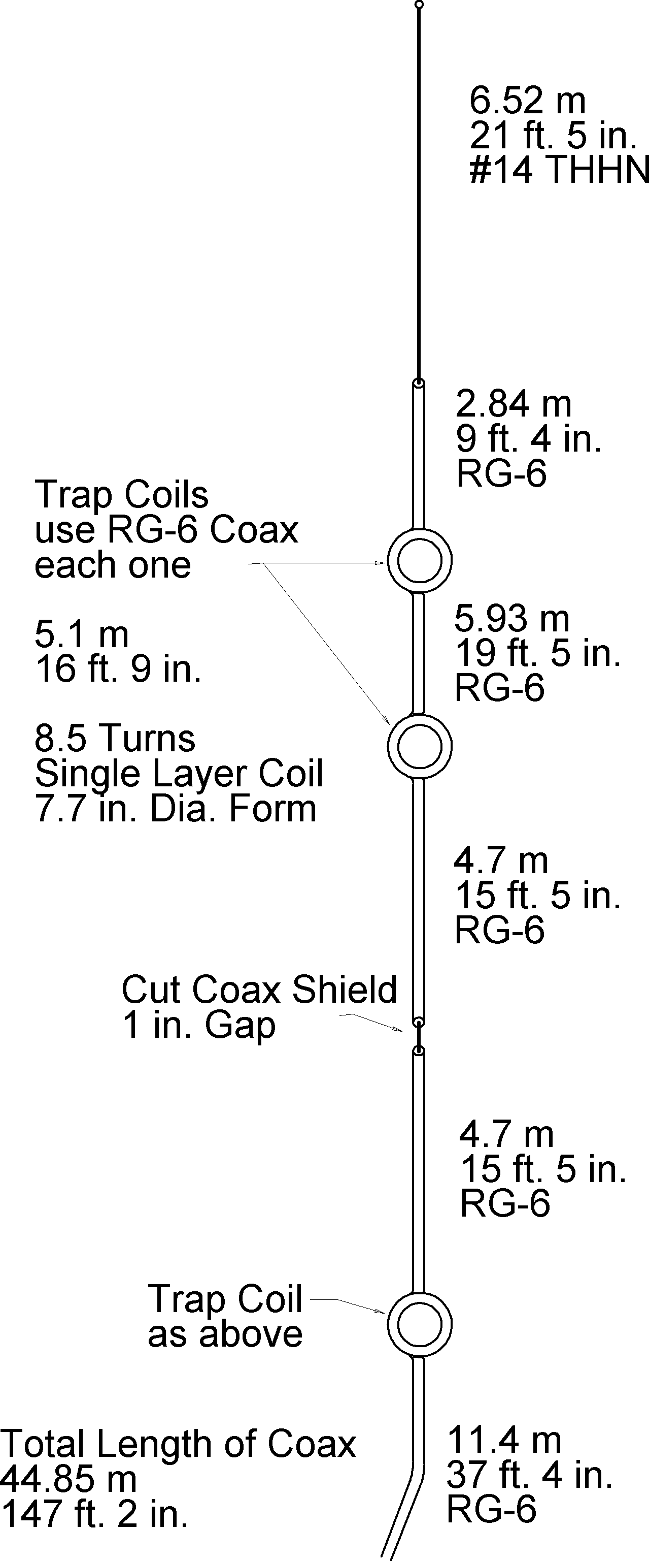
Once you grock the basic concept, that the break in the coax shield forces the currents onto the outside of the shield, it’s just a matter defining an effective length of the outer sections of coax that are to be radiating elements. We do this with resonant LC traps; the simplest version is just a coil of the coax itself to form the inductor L which resonates with the self capacitance C of the coil structure. When it comes to designing the traps, you may benefit from my attempt to distill some numbers in this Self_Resonant_Coil_Calculator. At this point we have to compute the actual lengths of the elements and cable sections. Keep in mind that the electrical length of the coaxial cable will be different inside and outside. For the transmission line properties we need to use the velocity factor of the cable to determine the correct electrical length, while for the radiating elements the wave velocity will be close to the speed of light, modified a few percent by any dielectric jacket on the coax.
The table below lists the parameters that we come up with using this conceptual starting point in the 1st Cut column. There are a number of competing constraints that we have to deal with. The natural impedance of the series fed collinear will be about 150 Ω and we have to match to the 50 Ω source. The length of the coaxial feed section is barely long enough to include the wound trap coils and the radiating sections of the dipoles for there to be any coax for separation between the top and bottom sections. The free-space collinear antenna will get maximum gain when there is about 0.4λ spacing between the tips of the dipoles.
One method of addressing the matching problem would be to use an odd quarter wave length section of transmission line and transform the impedance from the top section to how it would appear at the bottom feed point. With the quarter-wave sections the wave-guide is ana-reflective and gets a perfect match when the impedance of the line is the geometric mean of the terminating impedances. Starting from the 50Ω source with 75Ω line, the perfect match at the antenna end would be 112.5Ω. That must be the impedance of the lower dipole, ~73Ω, in series with the apparent impedance of the line to the top element, which means we would like that to be 112.5 – 73 = 39.5 Ω. We could get that apparent impedance if the we again use the odd quarter wave trick and arrange to have the top feed point have an impedance of 752/39.5 = 142Ω. That might be possible by feeding the top section off-center. The problem with all of this is, of course, that the perfect 360° phase match for top and bottom sections will no longer be correct if we use the odd quarter wave line.
This is where optimization comes in. There are many variables, several paths to improved performance, but no definitive way forward.
| Design Parameter | 1st Cut | Optimized | Units |
| Design Frequency | 14.1 | 14.1 | MHz |
| Design Wavelength | 21.27 | 21.27 | meters |
| Coax Type | RG-6 | RG-6 | |
| Coax Velocity Factor | 0.83 | 0.83 | |
| Coax Impedance | 75 | 75 | Ω |
| Height | 30 | 30 | meters |
| Length of line between top & bottom dipoles | 17.65 | 23.67 | meters |
| 1.0 | 1.34 | wavelength | |
| L1 Length of top ¼ wave section | 4.94 | 6.52 | meters |
| L2 Length of top lower ¼ wave | 4.94 | 2.84 | meters |
| L3 Length of bottom upper ¼ wave | 4.94 | 4.70 | meters |
| L4 Length of bottom ¼ wave section | 4.94 | 4.70 | meters |
| Length of coax for each trap | 3.6 | 5.1 | meters |
| Trap coil diameter | 256 | 196 | mm |
| Trap turns | 4.5 | 8.5 | turns |
| Trap L | 9.7 | 18.2 | µH |
| Trap C | 13.0 | 7.0 | pF |
| Separation between dipole ends | 0.5 | 5.93 | meter |
| Model Results | |||
| SWR | 1.78 | 1.09 | |
| Gain at 10° elevation | 2.88 | 4.18 | dBi |
| Radiative Efficiency | 44.9 | 57.2 | % |
The results of the optimization process significantly lengthen the connecting coax section and generate an off-center feed for the upper section as suggested above. Now, with the two sections no longer perfectly in phase, not as much energy is aimed at the ground plane on the horizon so the overall radiative efficiency of the antenna has increased, and the vertical pattern has broadened to 30° elevation.

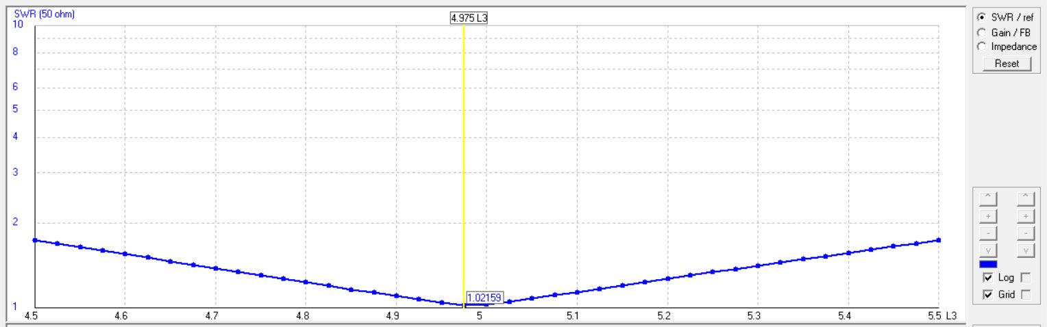
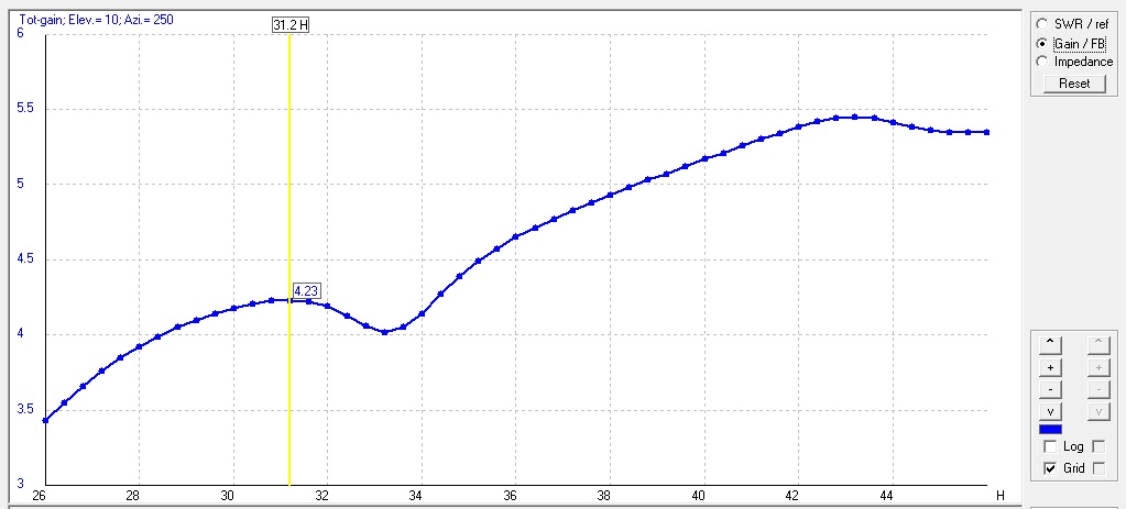
This is all looking good. The 4NEC2 model is here if you wish to play with it yourself. The model included the effects of the insulating jacket on the coax and the THHN top section, so I hope the numbers are close enough to have good results on the first build. Practically, it will be good to understand the sensitivity of the design to the exact lengths of the various sections and how one could finally tune the antenna once it is ready to be deployed. Tuning the lengths of the radiating sections may be accomplished by rolling the inductor traps a few inches up or down the feed lines. I deliberately miss-tuned the bottom section (L4) short by 0.15 m and then ran a sweep on the other quarter wave section, L3, to see if the tune could be recovered. The figure below shows indeed it is possible to recover the tune this way.
How does this design compare to other 20 meter vertical antennas? The table below shows a comparison of what you might expect with other architectures. There are a number of commercial verticals that probably fit somewhere between the 30 m high elevated dipole and the 5/8 wave ground plane antenna. The additional 4 dB in the low elevation DX window compared to the ground plane antenna is not to be sneezed at. There is no magic to be found that going higher and adding the second collinear element can’t beat for a vertical design.
| 20 m Vertical Antenna Type | Gain at 10° elevation (dBi) | Gain at 30° elevation (dBi) | Radiative Efficiency (%) |
| Optimized Vertical Collinear 30 m high | 4.18 | 1.14 | 57 |
| ½ Wave Elevated Dipole 30 m high | 2.94 | 1.39 | 57 |
| ¼ wave Ground plane with 64 radials 10 m long | 0.29 | 2.72 | 41 |
| 5/8 Wave Ground plane with 64 radials 10 m long | 1.1 | -0.13 | 44 |
Speaking of going higher (or lower), the figure below shows how the gain varies with the antenna top height. Going higher gets even a bit more gain.
What does all this performance cost? Looks like you can buy a 1000′ spool of RG-6 on E-bay for less than $100. Be sure to get the stuff with foam polyethylene dielectric with 0.83 velocity factor. You need a couple of flower pots for coil forms, a scrap of wire for the top section, and some rope to pull the thing up into your tree. And you need that tree! How it all works out will be in another post once I actually build the beast.

Gary,
How should I approach scaling your design to 6 meters? I already use a 2 element 6 meter antenna made from 14g THHN and 450 ohm ladder line for the matching and phrasing sections. I have heard that having the the two elements only an inch apart is not the best approach. And do your think a coax design will perform better?
73 and thanks Ken de AC3DH
p.s. I have a 3 element 6 meter design with 2/10 wavelength meander delay between elements, it tunes well, I just have to compare results on pskreporter.
Hi Ken,
I tried to make my design work on 6 m but did not have the best success. The problem was the air core trap coils were very “picky” to get to resonate where they needed to. My next attempt would involve using ferrites on the traps and choke coils to make them more like traditional chokes. I agree, it is better to have some space between the two half-wave dipoles. The interesting thing that came out of the modeling for the 20m version is that the best performance was not when the two antennas were perfectly in phase.
Hi Gary:
How do I make a “shortened” version for indoor condo (HOA restrictions) for 20 meters? No attic space.
Thanks de Scott, WY1Z