
I describe here a simple RF current probe that can be used to directly measure RF currents in wires and cables using an oscilloscope. The probe features “clip-on” operation, using a common clip-on RFI suppression ferrite core for the sensor coil. This was “take two” for coming up with a suitable current sensor for measuring the relative phase and amplitude of currents on the elements of my hex beam antenna. The first time I used a torroid I had laying around for the core. It worked fine but I had to partly dismantle the antenna to install the probe, and the signals were too small so I engineered this one from scratch, using some snap-on cores, also found in my junk box but readily available if you want to copy this.
The Plan
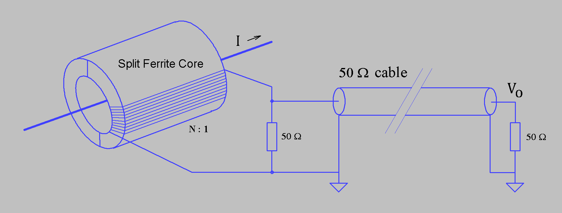
The diagram above shows how I built this. I used 10 turns of #28 wire on one side of a TDK ZCAT2132-1130 core. The core material is useful for RFI suppression in the 1 – 500MHz region, so chances are good it will work as a transformer through the HF bands. I carefully popped the core-half out of the plastic enclosure to wind the wires. I measure the inductance of the assembled coil and found it to be about 80 µH. The low frequency limit will occur when the L/R time of the sensor coil and sample resistor gets smaller than period of the waveform being measured. If I want to use this on the 160m band then I would like L/R > 1/1.8 MHz, which would imply R < 144Ω . Using a 50Ω sampling resistor, 50Ω cable and a 50Ω terminating resistor on the cable, terminates each end of the cable for a clean measurement and results in an effective sample resistance of 25Ω. High frequency roll off will likely show up because of stray shunt capacitance and/or core losses.
With 50Ω resistors and 10 turns the sensitivity should be: Vo = I/10 25Ω ==> 2.5 V/A OR 0.4 A/V
Typical signal levels for 5W on a 50Ω load would be… I2 R = 5W ==> I ~ 0.316 A==> ~0.79V Nice signal level.
Max current capability is limited by heating the 1/4 W resistors. V2 /50Ω = 1/4W ==> V= 2.5V ==> 1 A Max
The sensed wire will see the sampling resistor reflected back to the primary. In this case the resistor will appear as 25Ω /N2 = 0.25Ω For ~50Ω systems this should be minimal perturbance.
If you could live with less signal, wanted less perturbance for the system by the probes, or wanted to be able to look at larger currents, then more turns could be used. The likely trade-off would be poorer high frequency performance.
Construction

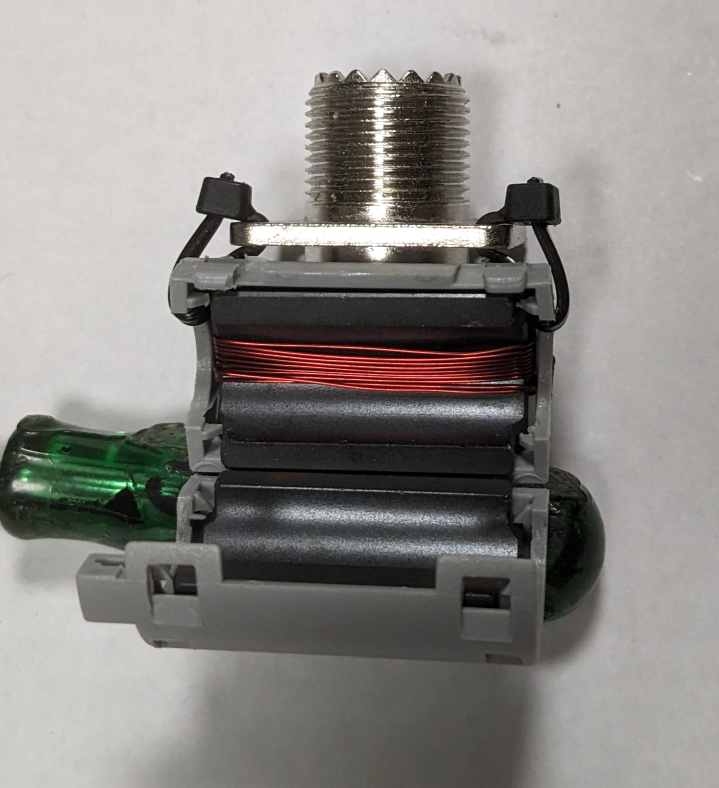
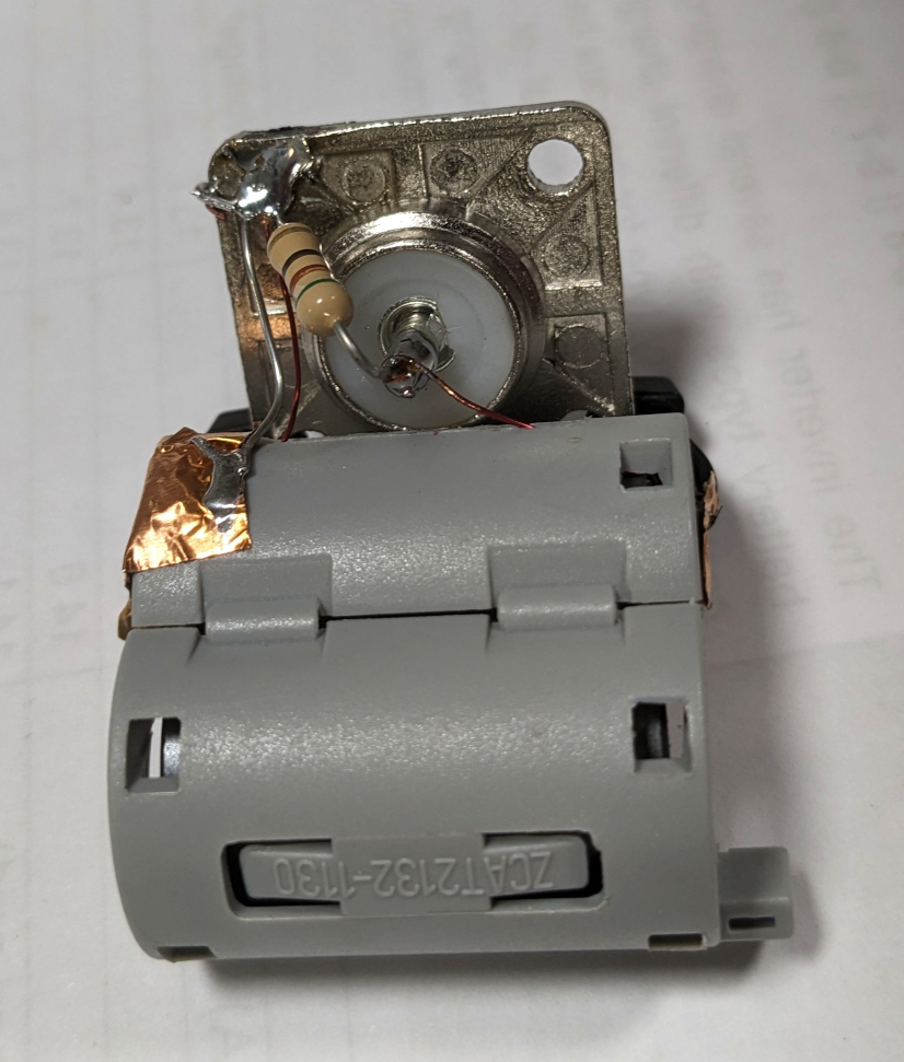
The pictures above show the construction technique. I used small cable ties to fasten the SO239 connector to the plastic case of the TDK snap-on ferrite. The ferrite section was removed and 10 turns wound on it. When putting it back in the case, the wires were routed through the holes around the plastic leaf spring. I covered the winding with a piece of copper tape. This electrostatic shield will kill any electrical capacitive coupling to the test wire. A small piece of rubber hose, split down the middle, is used to center the test wire inside the core and isolate the test wire from the copper shield. On the back, a 51Ω resistor connects across the SO239 and the coil wires connect to center pin and ground. The copper tape shield is also grounded.
How does it Work?
The ubiquitous NanoVNA can give us an idea about the frequency behavior of our probe. Exciting the primary and with a short and measuring the output you would expect roughly 10:1 voltage step down.

We get a fairly flat response from well-below the major ham bands, only beginning to fall off at 30MHz.
I can check the calibration using a dummy load. I arranged the set-up below to be able to compare several probes simultaneously and also to measure the voltage on the dummy load with the scope.


Sanity checks… Left image: Voltage on dummy load is 20Vrms, suggesting current is 20V/50Ω = 0.4Arms. Probe voltage is 1.019V yielding calibration factor of 0.393 A/V. As close as we can expect!
Comparing two probes, sensitivity is the same to within <2%.
I will be using the probes to compare RF current amplitude and phase on multi-element antennas. You could also use this probe to look for common mode currents on coax cables and wire harnesses.
