
My bamboo pull-up hex beam has been a work horse antenna for the last couple of years. It underwent a few changes from the initial design. I removed the 30 meter wires because the antenna was just too large to turn easily and get up and down between the branches with the space needed for the 30 meter version, and I added a set of 12m wires since that band is now open regularly as the solar cycle has heated up. I was going to add 10m wires as well, but discovered that the antenna worked on 10m without them! So you might think I would be satisfied, which I am, but I’m always looking for the next improvement. If I’m going to go through a big effort to build another antenna, I would like to know that I can expect at least a 3 dB improvement in gain over what I have now. So… it’s time to start modeling!
A good way to get another couple of dB would be to add another element. A feature of the standard hex beam is that the multiple bands do not interact very much. You can design a mono band antenna and expect that the nested multi-band version will work as well. Obviously we will check this assumption once we have a comprehensive model of the entire antenna, but for now, we are just going to concentrate on the geometry of the wires for a monoband version. The only requirement for a hex beam is that the wire elements are supported at the six spreaders and lie in the same plane. This implies a hexagonal geometry for the wire elements, commonly with insulating rope spacers between elements, generating a tension ring that defines the wire elements and is supported at the spreaders.
Single Band Geometries
In an effort to fully explore parameter space, I will show several design variations with performance evaluated at the current 11m height and at the aspirational 15m height. The baseline design will be the compact two-element hex beam. The three element designs will all be larger. The detail designs were all “discovered” using the 4NEC2 “evolve” method of optimization which employs a genetic algorithm to close in on a design. The beauty of the genetic algorithm is that it runs without much user interaction. The only tricky part is setting the weights for the “objective function.” After some experimentation, I set the Gain weight at 100, SWR at 100, F/B (front to back ratio) at 2, and F/R (front to rear ratio) at 10. You have to be careful not to get pulled into a large F/B ratio at the expense of everything else. In the end, there will be a narrow frequency range where the F/B is very high. The F/R ratio is more broad-band and and this metric still tells you what is good about the antenna, but is more forgiving when doing the modeling. The monoband models are done for the 20 meter band which will determine the overall diameter of the antenna. The models assume #14 coated wire such as type THHN commonly used for electrical wiring. Using bare wire would result in about a 3% increase in all dimensions.
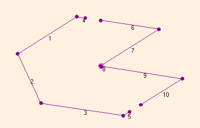
Baseline Two-Element Hex Beam
| Variable | Optimum (m) | Variable Description |
| D20 | 6.37 | Hex Diameter – 20.9 ft. |
| L20T | 0.323 | Tip length of reflector (wires 4 & 5) |
| L20S | 0.638 | space between driver and reflector tip |
| Driver Length | ||
| Reflector Length |
| Antenna Height | Gain | Elevation |
| 11 meters – Max forward gain | 10.3 dB | 26° |
| 11 m | 8.5 dB | 15° |
| 11 m | 5.9 db | 10° |
| 15 meters – Max forward gain | 10.7 dB | 20° |
| 15 m | 10.2 dB | 15° |
| 15 m | 8.1 dB | 10° |
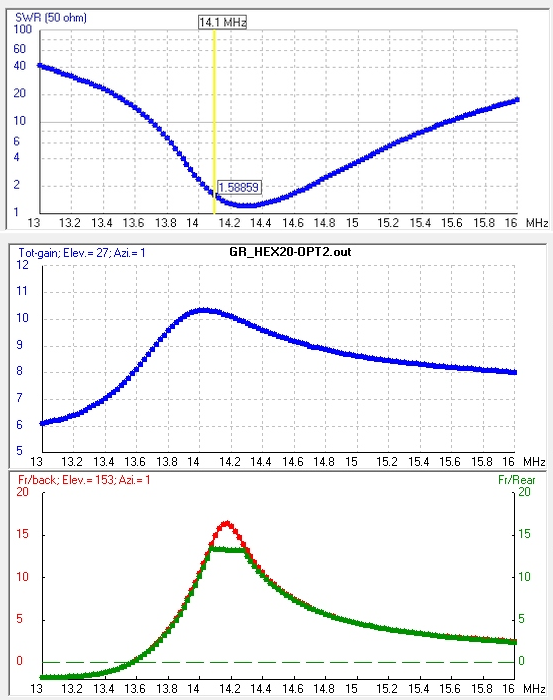
The two-element hex is the baseline with which to compare any new design. The beauty of the hex is its compactness. The 20 meter hex turns in hex diameter of only 6.4 meters. All of the three element designs will be larger.
Three-Element Big and Simple
| Variable | Optimum length (m) | Variable Description |
| D20 | 9.848 | Hex Diameter – 32.3 ft. |
| L20S | 2.722 | Director space to driver |
| L20SR | 2.253 | Reflector space to driver |
| Director Length | 9.328 | 367.2 inches |
| Driver Length | 9.848 | 387.7 inches |
| Ref. Length | 10.26 | 404.1 inches |
| Antenna heights | Gain | Elevation |
| 11 meters – Max forward gain | 11.8 dB | 25° |
| 11 m | 10.2 dB | 15° |
| 11 m | 7.6 dB | 10° |
| 15 meters – Max forward gain | 12.3 dB | 19° |
| 15 m | 11.9 dB | 15° |
| 15 m | 9.8 dB | 10° |
For the simplest three element design the driver extends across the diameter of the hex, and for that reason is also the largest design with the hex more than 10 m across for the 20 meter antenna. Forward gain is about 2 dB more than for the two element baseline version.
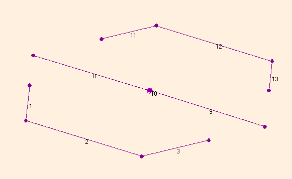
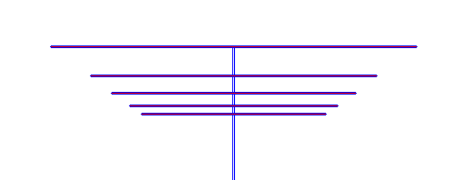
Three Element – Small, Full Shape Flexibility – Double W
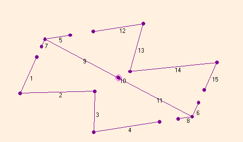
Adding capacitive tips to the driver and folding the director and reflector elements allows for a more compact design. Instead of just three free parameters, now we have seven. This is where an overnight run using the “evolve” genetic algorithm works very well.
| Variable | Optimum Length (m) | Description |
| D20 | 7.66 | Hex Diameter – 25.2 ft. |
| L20T | 0.988 | Driver Front Tip (wires 5 & 6), 38.9″ |
| L20TR | 0.541 | Driver Rear Tip (wires 7 & 8), 21.3″ |
| L20S | 0.894 | Space Tip to Director, 35.2″ |
| L20SR | 0.729 | Space Tip to Reflector, 28.7″ |
| L20F | 0.617 | Director – wire to center, 24.3″ |
| L20FR | 1.278 | Reflector – wire to center, 50.3″ |
| Director Length | 10.52 | 414.25 inches |
| Driver &Tips | 10.72 (sum) | Dia. 301.7″; Tips 60.2″ each |
| Reflector | 10.72 | 422 inches |
| Antenna height | Gain | Elevation |
| 11 meters – Max forward gain | 11.8 dB | 25° |
| 11 m | 10.1 dB | 15° |
| 11 m | 7.5 dB | 10° |
| 15 meters – Max forward gain | 12.2 dB | 19° |
| 15 m | 11.8 dB | 15° |
| 15 m | 9.75 dB | 10° |
Losing 2.2 m from the diameter did not significantly reduce the performance of this three-element hex version. The only disadvantage with this design are the two tension members that are required to pull the reflector and director elements in toward the center to make the ‘W’s.
Between the two extremes of the “big simple” and the “double W” models there are options for adding capacitive tips to the drivers, but leaving one or both the reflector and director at the full hex diameter, only one ‘W’. When I tested these geometries, the results were not satisfactory. Although the geometries did “evolve” into marginally useful antennas, the added constraints resulted in poorer forward gain and poorer band definition from F/R and SWR metrics.
The best of this lot was when just the director was pulled inward in the middle and the reflector stayed on the hex diameter. This model found an optimum at 7.7 m diameter with 11.6 dB forward gain and good SWR, but poorer F/R characteristics than the other three element geometries.
The Full Five Band Antenna
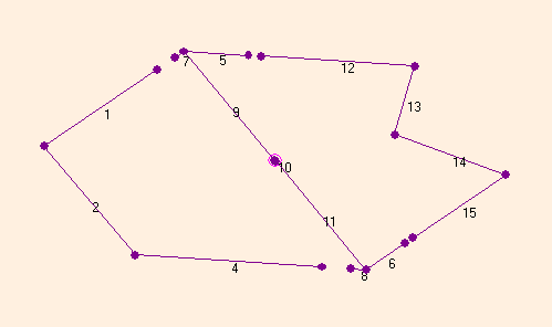
Based on the considerations above, I chose the “double W” to extend to multiple bands. I like the fact that the compact three-element design is only a little more than 4 ft. larger than what I have now. Going to the multi-band model, I included the transmission line feed to the radio and the lines between the multiple elements. To begin with all the lengths of the wires for the higher bands were scaled inversely with frequency.
Now the antenna is getting pretty complicated with lots of segments and variables and optimization runs can take a while. One issue that comes up with hex beams in general is that the upper band wires naturally end up pretty close to one another if you use the inverted umbrella spreaders. In the model, I tried to give as much space as I thought I could to the 10m and 12m wires, but they naturally get close together when supported by the spreaders.
To maintain tension in the spreader they need to have a convex inverted umbrella shape, but to get more spacing for the 10m band you would rather have the bend in the spreaders go the other way. The separation between the wires for the model is up to me, but I need to think about physically how that will work. This is a case where model run can tell us how much this matters. I was surprised that even a relatively close spacing did not change the performance of the 10 meter band very much.
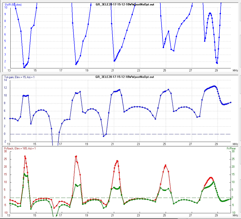
Dealing with all five bands and the interactions between them, our best diagnostic is a multi-band frequency sweep. Once all of the additional band wires were added to the model, the frequency sweep shows the SWR and the gain profiles for each band. The ham bands are plotted with close-spaced points on these graphs. The gain was measured at 15° elevation with the top of the antenna at 11 meters. One thing you can see immediately is that the 15° gain is better on the higher bands that it is on 20 meters. The antenna is close to “high enough” at 15° for the upper bands.
The SWR was good on the 20m band; that band did not object to all of the other wires we added. The upper bands do not have as good SWR.
To “touch up” each band, it is possible to move the resonance point up/down in frequency by changing slightly the scaling compared to the 20m band. But frequency scaling will not improve the SWR issues, instead you just have to optimize the the 7 (or 6 if you leave the hex diameter fixed) parameters for each band one at a time.
With a bit of work, it was possible to bring down the SWR somewhat on the upper bands while maintaining decent gain profiles. In this run 10 meter band has a rather sharp resonance and the upper sections of the band are not covered, but it should be okay in the DX portions of the band, perhaps with the aid of a tuner.
All of this culminates in the comparison shown below where you can see the effects of both the added element and on the antenna height.

At this point I spent quite a while trying to get all of the bands to look good. This was a frustrating exercise for the 10m and to a lesser extent the 12m band wires. Eventually I realized part of the problem was the extra “stub” of feed line that went past the 10m element all the way up to the 20m element. The other elements looked almost like open circuits to the 10m frequencies, but the feed cable adds a somewhat random reactive component to the mix. Feeding from the top (20m element) move the problem to the 20m wire because there was still a “stub” of feed line there, this time going down to the 10m wire. However the problem was not as bad because the stub length was less of a fraction of a wavelength for 20m that it was for 10m. The final compromise was to put the feed point at about the 17m or 15m wire locations and change the interconnecting lines between wires at the antenna to a nominal 100 ohm impedance (typical of zip cord).
As I got closer to a real design, I was also looking at the antenna site and the overall diameter constraints. Not surprisingly, I would really like the antenna a little more compact! Hence, I again looked at the 20m wire, since that is the largest structure. I was curious if I could reduce the hex diameter a little and still recover an effective design by optimizing the other six parameters. The process was to change the hex diameter in 0.1 meter increments and then run the hill climbing optimizer at 14.1 MHz for the six other variables. It was always possible to get a reasonable resonance, but resonance band characteristics changed markedly as we went from too-small to too-big for the basic hex.
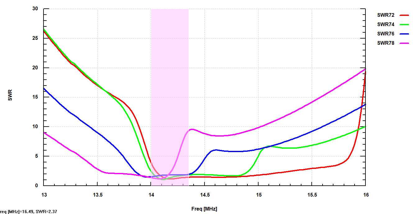
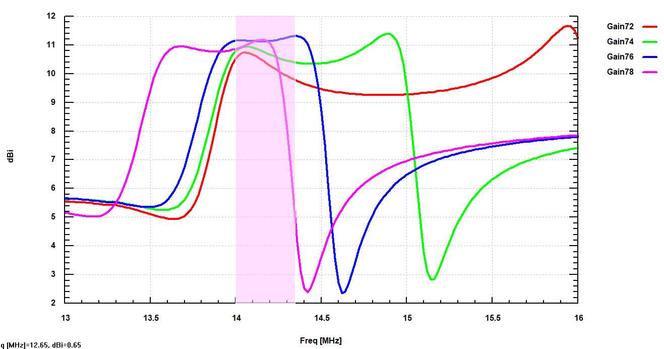
Although the optimizer found a reasonable operating point at 14.1 MHz, the SWR for the hex that was “too big” took off mid-band to unacceptable levels. The antennas that were built on a hex that was “too small” had low SWR that extended well past the end of the band, and had useable forward gain also well past the upper band edge. However, especially at the upper edge of the band, the forward gain was not as good as for the more optimum 7.6 meter hex build. Note that “pushing” the diameter away from the optimum can result in a wider bandwidth.
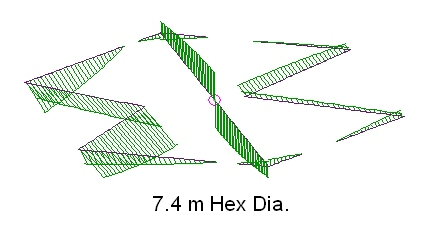
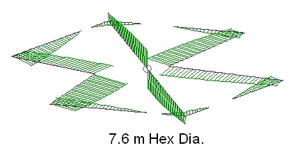
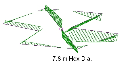
When the hex is too small, the director does not have as much current as the other two elements. When the hex is too big, then the reflector has less current. Balanced in the middle, all wires have similar current magnitudes.
Making the hex just a little smaller (0.2 meter less) is not particularly detrimental, but there would need to be a good reason to do it; you will only pick up 8 inches of the nominal 25 foot diameter.
New Parameters
I’m going to pause here and discuss how the parametrization that you choose when defining the antenna geometry can influence the optimization procedure. I was getting very frustrated because the optimization runs were taking a long time and I could not intuit where good results would be coming from. My parameter list included the hex diameter (1), the depth of the ‘W’ pull-ins (2), the length of the tips on the driver wire (2), and the length of the spacers between the driver tips and the reflector and director (2), for a total of 7 parameters for each wire. This works fine for a “dumb” optimizer, but the parameterization lacks much intuition into the physics. It is almost impossible to help the process along based on human understanding and intuition when, for example, changing the length of a wire tip will not only change the effective length and resonant frequency for the wire, but also the coupling to its neighboring wires. Optimization runs happen at single frequency. If I want to “flatten out” the pass band a little — how would I do that?
A parameterization that is more physically intuitive uses these variables: The hex diameter (1), the wire length for the three elements (3), the tip fraction in front of the driver (1), the depth of the ‘W’ pull-ins (2). There are still seven parameters. The driver wire length includes the wire from the feed point plus the total length of the tips. Besides making the change of parameters, I also normalized them all to the design wavelength so all of the parameters are dimensionless numbers. This makes it easier to compare between bands. Now, the three element-length numbers are similar to a Yagi design using straight elements, where commonly the reflector is a few percent larger than the driven element and the director is a few percent smaller. The other parameters can be thought of as “coupling adjusters” that modify the interaction between the three elements but don’t have much effect on the resonant frequency.
Here is a listing of the parameters for the 20 meter wire:
WL20=3.e8/14.1e6 = 21.2765957446809 Design wavelength
20 m band parameters
FD20 = 0.36 Hex Diameter Fraction
FF20 = 0.022445 Front ‘W’ pull-in radius in wavelengths
FR20 = 0.068981 Rear ‘W’ pull-in radius in wavelengths
FDIR20 = 0.491 Director length in wavelengths
FDRV20 = 0.497 Driver length in wavelengths
FREF20 = 0.503 Reflector length in wavelengths
FT20 = 0.981813 Fraction of tip in front of driver
20 m band “construction” parameters used in the model geometry definition. Physical lengths of tips and spacers specified using the parameters above.
D20=WL20 * FD20 = 7.65957446808511
DIR20=WL20 * FDIR20 = 10.4468085106383
REF20=WL20 * FREF20 = 10.7021276595745
DRV20=WL20 * FDRV20 = 10.5744680851064
L20F=FF20 * WL20 = 0.477553191489362
L20FR=FR20 * WL20 = 1.46768085106383
L20T=FT20 * (DRV20 – D20)/2 = 1.43094022340426
L20TR=(1-FT20) * (DRV20-D20)/2 = 2.65065851063829E-02
L20S=(D20 – DIR20 + 2*sqr((D20D20/16 +(0.433D20 – L20F) * (0.433D20 – L20F))))/2 – L20T = 0.599910623958
L20SR=(D20 – REF20 + 2*sqr((D20D20/16 +(0.433D20 – L20FR) * (0.433D20 – L20FR))))/2 – L20TR =1.1140402258
This effort revolutionized the design process! The three element-length parameters set the position of the resonance in the band and set the bandwidth by the the amount of variation between the driver and the parasitic element lengths. It was possible to adjust the “match” with the other three variables without changing the position of the resonance in frequency space. Rather than using the optimizer for every run, it was possible to adjust the relative bandwidth and band frequency just by making educated guesses for the three element-length parameters. With this new parameterization you can change, for example just the hex diameter but leave all of the other parameters the same. You will actually be changing several “construction” parameters, such as the tip lengths on the driver and the length of the spacers ties between the wire element on the hex periphery, but you will be leaving the length of the three antenna wires unchanged. When a band needed full optimization for a good match, only three parameters needed to be optimized rather than six, so the process was much quicker.
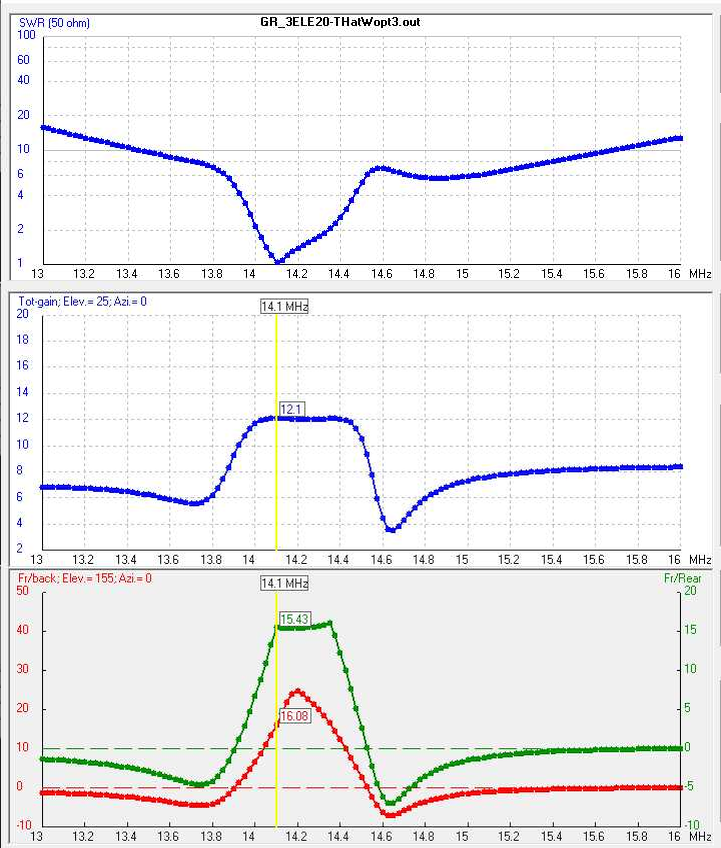
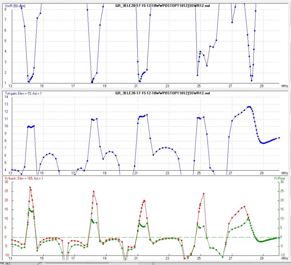
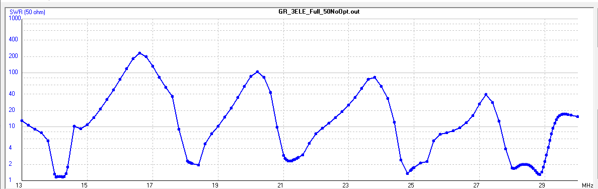
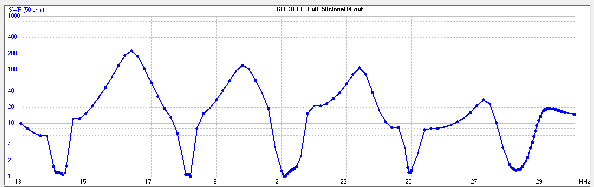
Shown below are (1) sweeps for the initial clone of the 20m single band parameters to the full antenna including the connecting transmission line segments and (2) the fully optimized 50 ohm antenna.
Getting Real
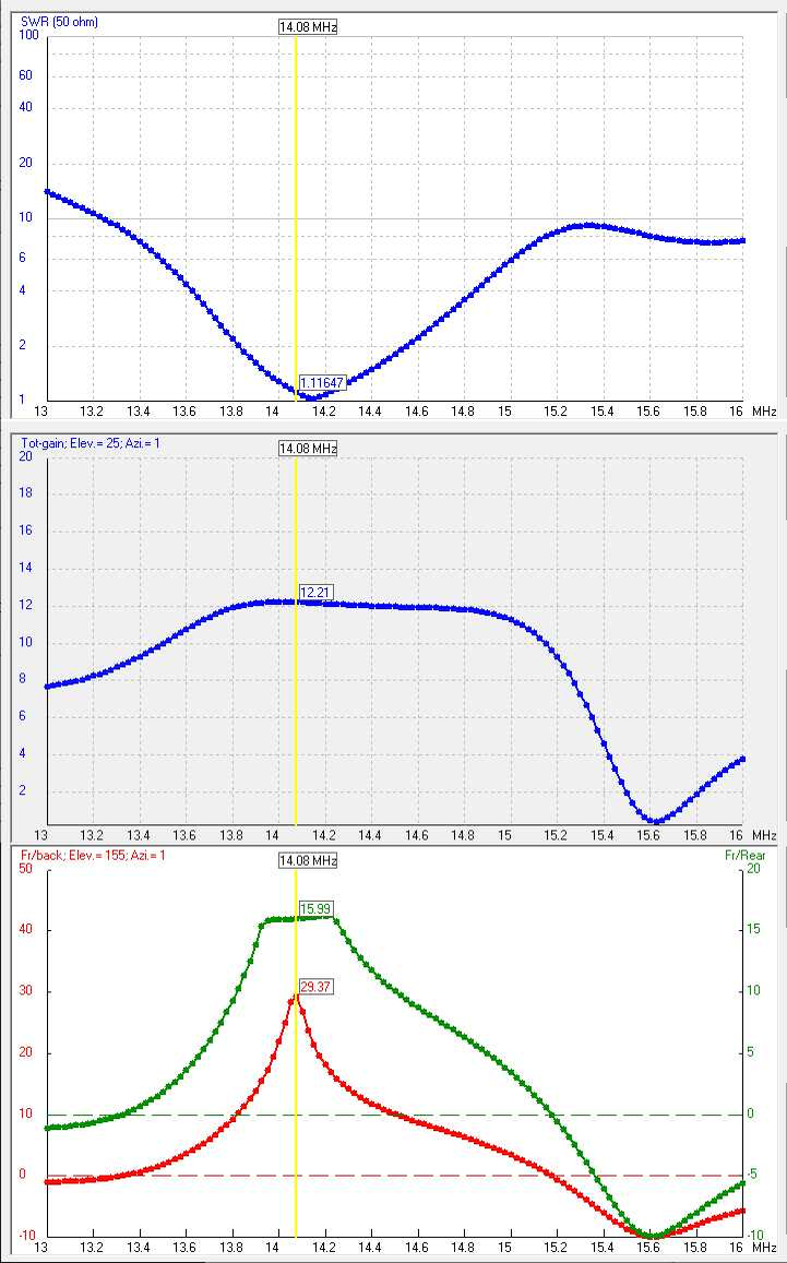
The last consideration for the antenna I want to put up is that I plan to drive it with the same piece of 75 ohm cable I’m using now. I carefully measured its electrical length at 49.45 m +/- 0.05m using the NanoVNA TDR feature and also using my scope and a fast pulse. In the NEC model it mattered quite a bit if you changed the transmission line length by a meter, so I pulled the old antenna down and disconnected the cable so I had a nice reflection from the open end to be able to make an accurate measurement. With the correct cable as part of the model, I re-optimized each band just as I did for the antenna driven with a 50 ohm source. In addition, I again tried to shrink the 20 meter band diameter. This time when I shrank the hex diameter, you could see the wires curl around further and the spacers got smaller. The band position didn’t change too much, and optimization of the remaining three “coupling adjuster” parameters could be used to attempt to regain a good match. Using this method, I was able to reduce the overall diameter by almost a foot, but in the process the forward gain went down about 1dB, so definitely a trade-off.
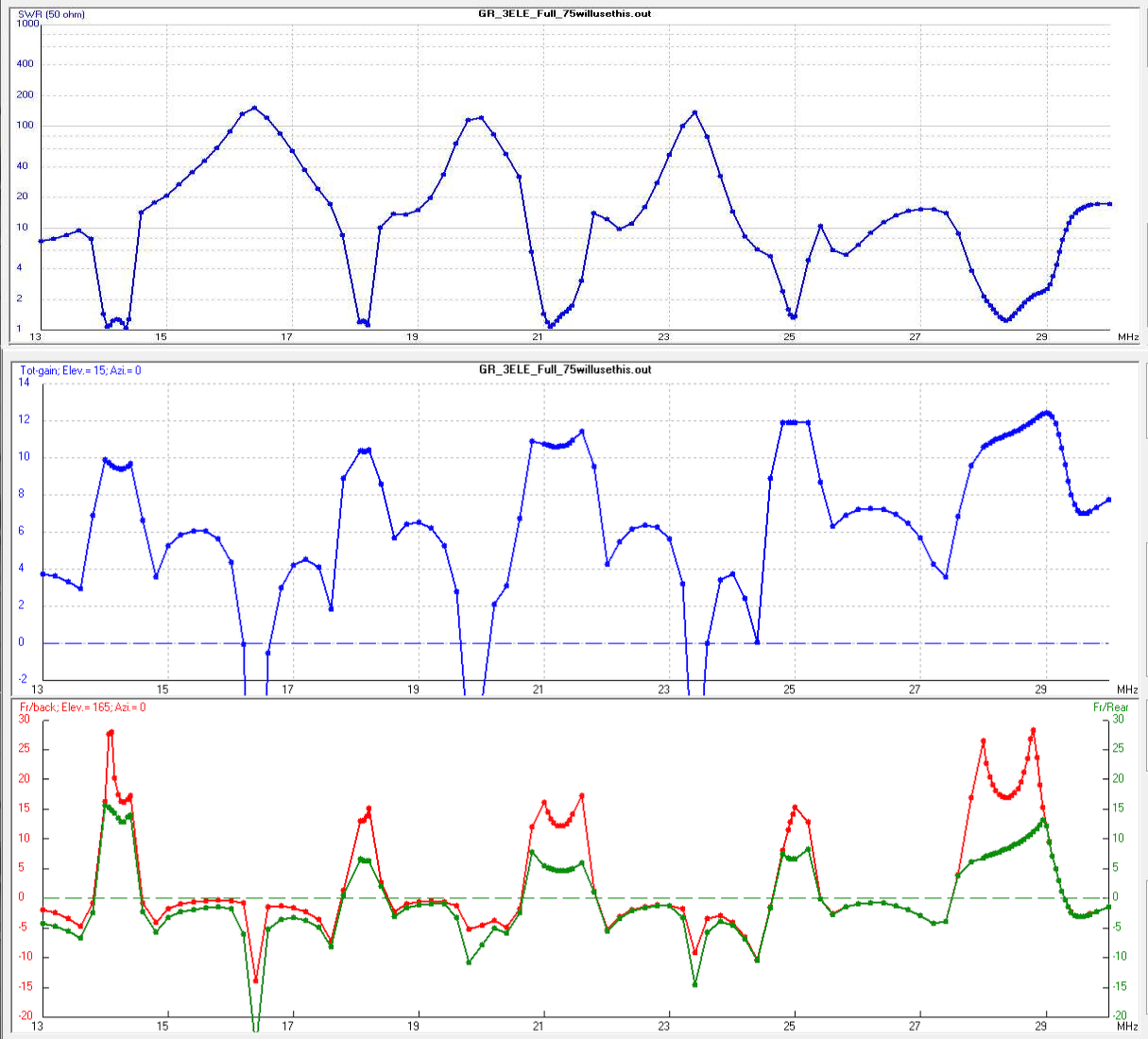
The charts above show the SWR sweep and the Gain and F/R&F/B sweeps for the antenna I intend to build. This was optimized for good SWR into 50 ohms at the transceiver while being coupled with 49.5m (electrical length) of 75 ohm cable. Almost no modification of the three element length parameters was required to change over from the 50 ohm antenna to this one. Instead, I just optimized the amount of “pull-in” on the outside elements and the way the tips are placed at the ends of the driver wires. These parameters effected the gain and resonance frequency only marginally, but they change the driving impedance, the reactive component particularly.

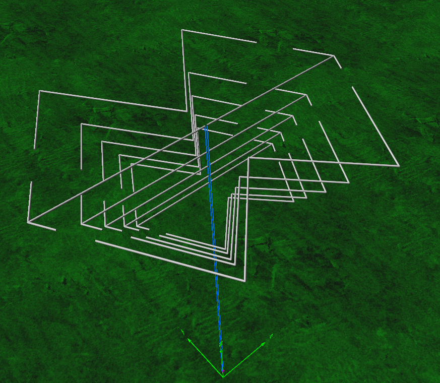
The image above shows the pattern on the 15 meter band when the antenna is 15 meters up in the air, a classic second vertical lobe for an antenna one wavelength up. Note that the “pull-in” on outer wires for the various bands appears somewhat random. I believe that came about from the matching requirement to the specific length of 75 ohm cable I will be using, but this illustrates how the tuning works with this antenna. Also notice that the capacitive tips on the drivers are almost entirely in the forward direction. One simplification might be to enforce that condition and just bend the wire forward – eliminating on of the free parameters. This can be never ending…
The Recipes
Going back from the seven model parameters to the length measurements you need for construction requires a bit of arithmetic. To keep track of my progress and do the housekeeping, I made a little Excel spreadsheet that includes the actual lengths of everything measured in both meters and inches, for both my specific 75 ohm cable installation and for the 50 ohm case. That is where you can find numbers for all of the lengths needed. Also in the links below are the 4NEC2 models for the 50 ohm case and my special 75ohm cable case. If you decide to use these, everything you want to change is on the “Symbols” page. Should you decide to build one of these, I would like to hear from you.
