
The IC-745, like the older ICOMs, is built very robustly with parts that you can see without a magnifying glass, and which you can check with standard meters. The schematics are available on-line, the old ICOMs come up for sale on e-bay regularly, and there are support groups on line to help out when problems arise. The major problems are know and the fixes are documented. Although the IC-751 has the advantage of serial computer control that the IC-745 does not have, the IC-745 can also be a very good first HF radio for those willing to do a little restoration. These radios made in the early 1980’s are some of the first all solid state transceivers and represented state of the art technology when they came out. To this day, they perform well for the functions that they were designed for, mainly SSB and CW communications. However, the ham world changed in the last thirty years with the advent of the PC and the digital modes.
There are a few things that you need to accomplish to have the best possible operation on digital modes with the old radios.
- Computer control of the radio (CAT). Sorry, we have to give that one up on the IC-745. It just was not made with serial control in mind. Arduino freaks could conceivably make that work – but you would be taking on a giant project.
- Sound Card connections. Getting audio to and from the transceiver is required for digital modes.
- Ensure stability and true frequency calibration. The narrow band digital modes care more about frequency shifts and drifts of a few Hertz which voice communications would never have noticed.
- Extras like an RTL-SDR panadapter can provide modern functions to vintage radios.
Having given up on #1 lets get on to the others.
Sound Card Connection for the IC-745

To work the digital modes you need to be able to connect signals to and from a computer sound card. It is always possible to use the MIC connector, but then you will be always swapping out this connection when going between voice and digital modes. Better is to use the rear 24 pin ACCessory connector. The audio output from the IC-745 can be found on Pin-4 of the ACC connector. Ground is on Pin-8 next door. I directly wire an audio cable from Pin-4 to the sound card Line IN. It is a little harder to figure out where to put the sound card Line OUT. This transceiver was never designed to have anything other than a mic input, so we will need to play tricks. The MODE wire, Pin-5, is close to what we want. If you follow it, it comes from the one side of the MIC gain potentiometer. That seems promising until you realize that this point is the output of the mic preamp (wire MIC1). My solution was to sum the mic preamp and the MODE wire together through resistors at the high side of the mic gain pot. There is already a resistor on the MODE wire, R75, but none on the MIC1 wire.
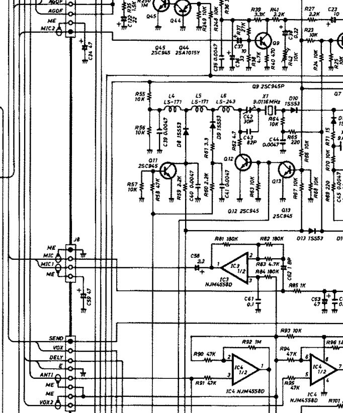
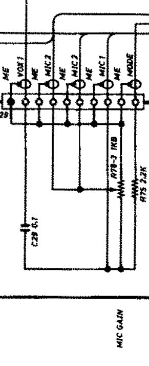
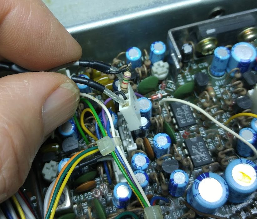
If you stare at the bits of schematic I’ve provided, you can figure out this logic. I added a 1.5kΩ summing resistor to the MIC1 wire at the J8 header. This allows the MODE wire to be an audio input controlled by the MIC Gain knob yet still allows signals from the MIC preamp to also be used. The photo below shows how this was done on the J8 header.
With this simple modification, the ACC connector Pin-5 will work as the audio input form the sound card Line OUT. The VOX will also work using the sound card audio to key the rig. The MIC connector is free for the mic. Just be aware that the ICOM mic is always live, so if you do leave it plugged in, keep quite when transmitting via the PC sound card.
Improving Frequency Stability on the IC-745
These early ICOM radios use a phase locked loop (PLL) stabilized VFO, which was state of the art when they were made. Unfortunately, the PLL circuits used some plastic trim capacitors which are guaranteed to deteriorate over time. They need to be changed out if they haven’t been already. A very good description of the trimmer replacement and other useful mods and adjustments written by Frank of W3UHF can be found here. Even with the trimmers replaced, the IC-745 suffers a small problem caused by thermal changes near the crystals that control the master oscillators in the radio. The problem is worse with radios with the internal AC power supply. The issue is that when the fan comes on to cool the output transistors, air is pulled in the vents in the bottom of the enclosure and the cool air flows over the crystals. They change frequency just a little. When the fans stops, the crystals warm up again and the frequency drifts back the other way. I found that isolating the crystals from the air flow with some Styrofoam “peanuts” help quite a bit. There are two crystals to protect for the 1st and 2nd local oscillators. I still see a little general temperature drift, but no longer on the ~1 minute time scale that made it difficult to hold a digital QSO.

The architecture of this radio makes it difficult for the TX and RX frequencies to be spot on. This is mainly an issue on the PSK31 mode where being off by 10Hz will mean you may have difficulty making a contact. I did the best I could with the LO frequency adjustments, but finally just resorted to using the RIT control to get things perfect.
RTL-SDR Panadapter pick-off point

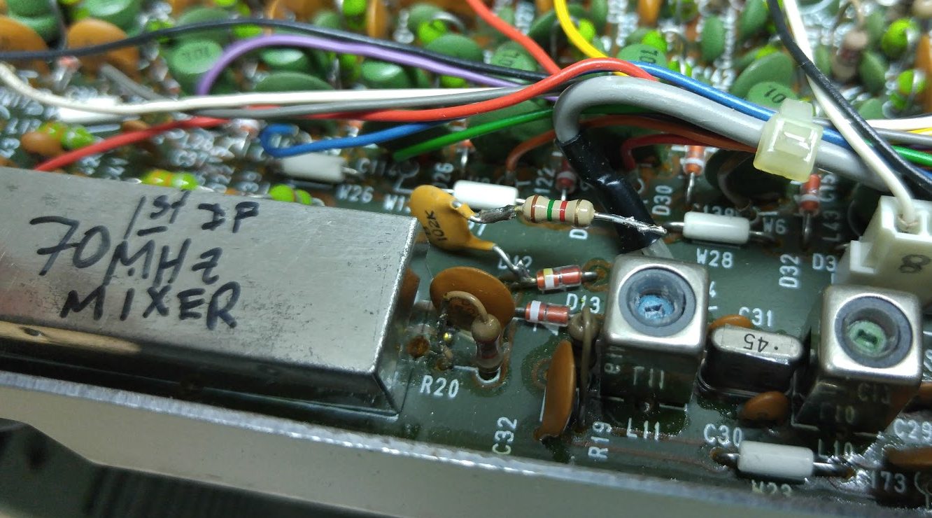
The 70 MHz first IF frequency on the IC-745 provides the perfect place to grab a signal for the ubiquitous RTL-SDR dongles that are available. With the RTL-SDR you can quickly see all of the signals on the entire ham band to which you are tuned. A little study of the schematic shows the appropriate pick-off point. You want to be right after the 70 MHz mixer but before the IF filters so that the dongle can see a wide bandwidth. In the schematic fragment, the point I chose was across resistor R20. I didn’t want to disrupt the circuit, yet need to get signal into a piece of co-ax, so opted for a 100 pf and 1.5kΩ series coupling into the 50Ω co-ax. I did not see any deterioration of the IC-745 signal doing this. In the photo you can see capacitor and resistor tacked in. The sub miniature coax, since moved over to my IC-751A, found ground on the bent over leg of R20.
Go forth and have fun!

Hi – great info, and thanks. Kone question – is the 1.5k summing resistor simply added in series with the MIC1 line at J8? Picture suggests so but is not quite clear. Thanks!
Hi Lawr, Yes, the 1.5k resistor is just to so your audio signal doesn’t try to drive the OUTPUT of the MIC preamp, so it is just in series with the MODE wire coming from the rear connector.
Good Luck.