
If you have success with any of these modifications, please drop me a note to let me know your experiences.
Update 11/09/2020: Added section on adding CW KEY and PTT lines using a USB to Serial RS-232 port.
Update 10/24/2023: Added section describing how to add 3.5mm audio jacks instead of using 24 pin AUX connector for sound card audio I/O.
The 30 year old ICOM HF radios still have a bit of life in them if given the chance. I’ve managed to work all of the states and more than 200 countries using the digital modes with my old IC-751A in the last couple of years. A few small modifications have helped to run digital modes with this radio. This post will describe in detail the physical modifications and additions that I’ve done to the IC-751A to use it with a computer running FLDIGI or similar digital-mode programs. These mods should work for the IC-751 as well.
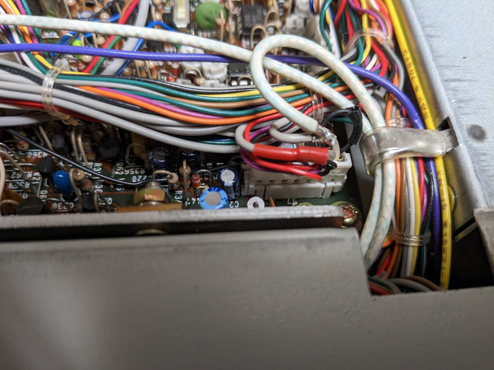
Sound Card Audio Connection – using 24 pin AUX connector: Without modifying the radio, you have two choices. You can use the rear panel auxiliary connector, Pin-5 for audio input, but you get no front panel knob to control the input level, nor can you use the VOX for PTT control. Or you can use the mic connector, but then you will always be disconnecting / reconnecting when you want to switch between the microphone for phone and the computer for digital modes.
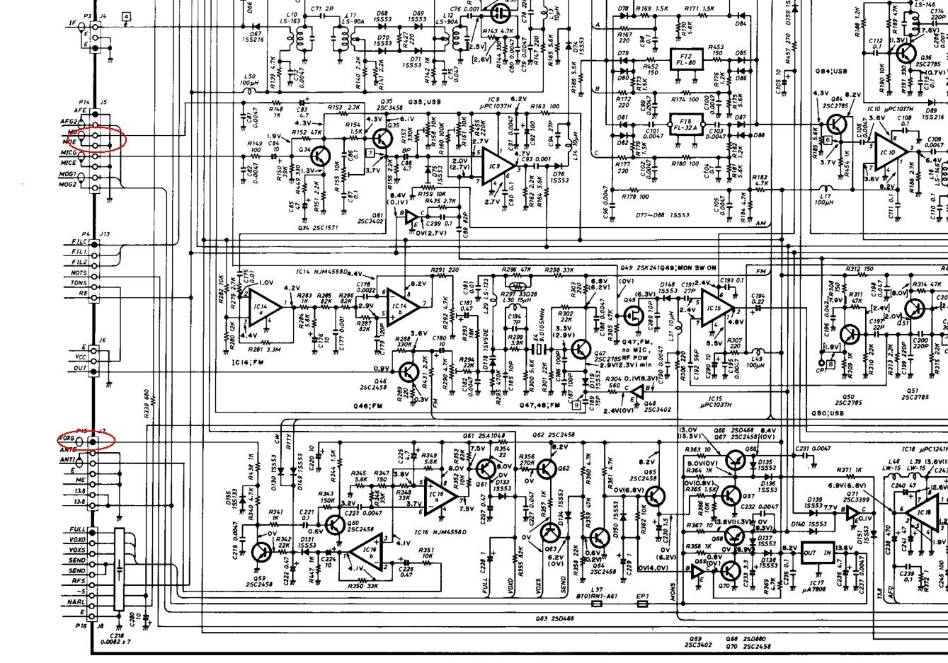
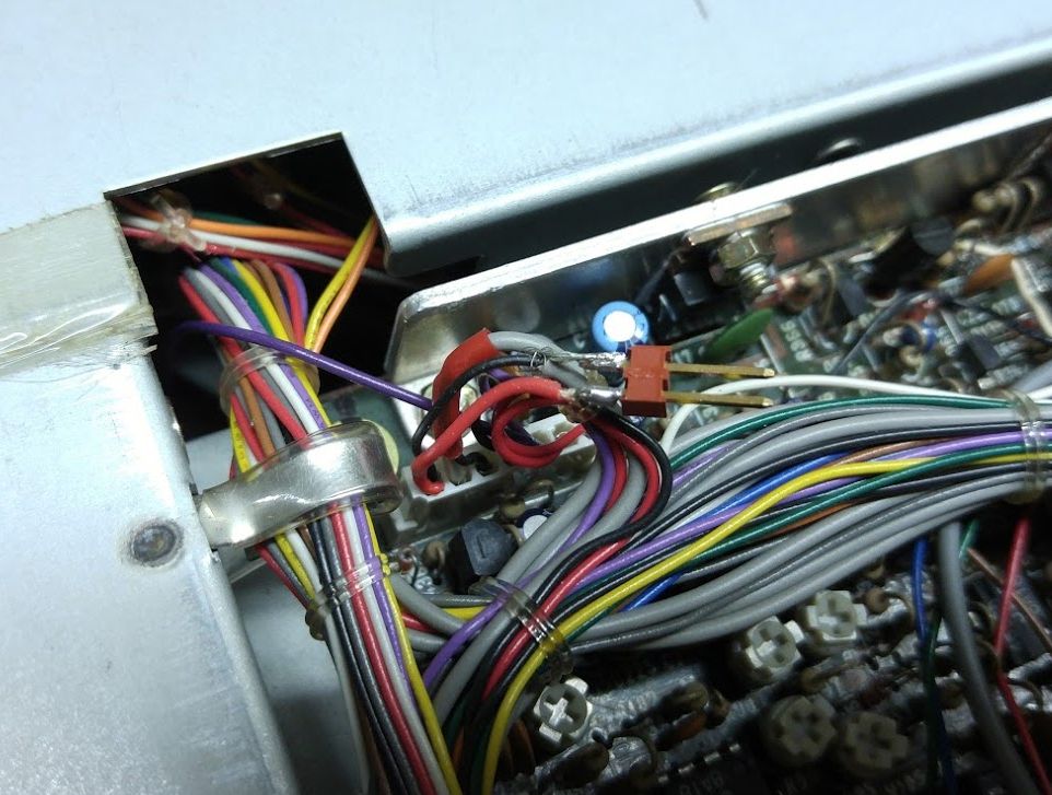
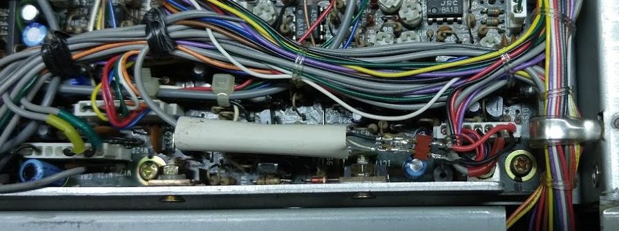
For these reasons, I made a small modification to the 751A wiring that allows use of the rear connector, but plumbs the audio input signal through the MIC GAIN control and VOX circuits. The pictures show the plan. The wire from Aux Pin-5, the trace labeled MO, is lifted from connector J5 and attached to trace VOXG on J7. I did this with the aid of a two-pin connector so I could easily back up if I needed to. As the picture shows, I picked off the ground from the shielded but ungrounded VOXG cable and also tapped off the connection at J7 Pin 1 for the two-pin connector for the MO wire. The last picture shows the MO wire rerouted to the two pin connector, ready to be covered up with shrink tube.

Wired this way, both the VOX GAIN and the MIC GAIN controls will affect the level of the audio input signal. Using the VOX is a handy way to key the rig when transmitting using the digital modes, so you should turn the VOX GAIN up enough that the digital audio signals from the PC reliably trip the VOX and key the transmitter. Then you can use the MIC GAIN control to fine tune the audio level into the transmitter. For many digital modes it is important to keep the RF amplifier linear and not overdrive it. I achieve this by leaving the RF PWR level control turned up all the way while using the MIC level control to then set the power output. If the rig wants to throttle your output, it will do so by raising the ALC level. This can happen if the SWR match is poor, or if you try to drive the output beyond the capability of the rig or beyond the RF power setting. Ideally, the ALC level reading on the meter should never lift off of zero for clean digital transmissions. But this means watching your output power level and using the MIC GAIN knob to adjust the input level, rather than throttling with the RF PWR control.
To complete the connections to your sound card, you will need to wire up the rear panel 24 pin auxiliary connector. You should connect “Line-IN” of the sound card to the AF OUT on AUX pin 4 and the “Line-OUT” on the sound card to the MO line on AUX Pin 5, using the common ground, AUX Pin 8, for both signals.
Sound Card Audio Connection – using 3.5mm audio jacks: The wiring is similar to what is described above, but rather than using the wires already in place to the 24 pin AUX connector, wiring is added to a pair of 3.5mm audio jacks mounted to the AC line blank panel on the 751A.
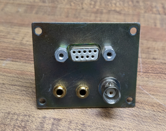
The TX In wiring is same as mentioned above, but the picture shows going directly to the connector without the small plug. I used some small white coax I had on hand for the audio cables. Again ground the audio shield to the VOXG cable’s shield.
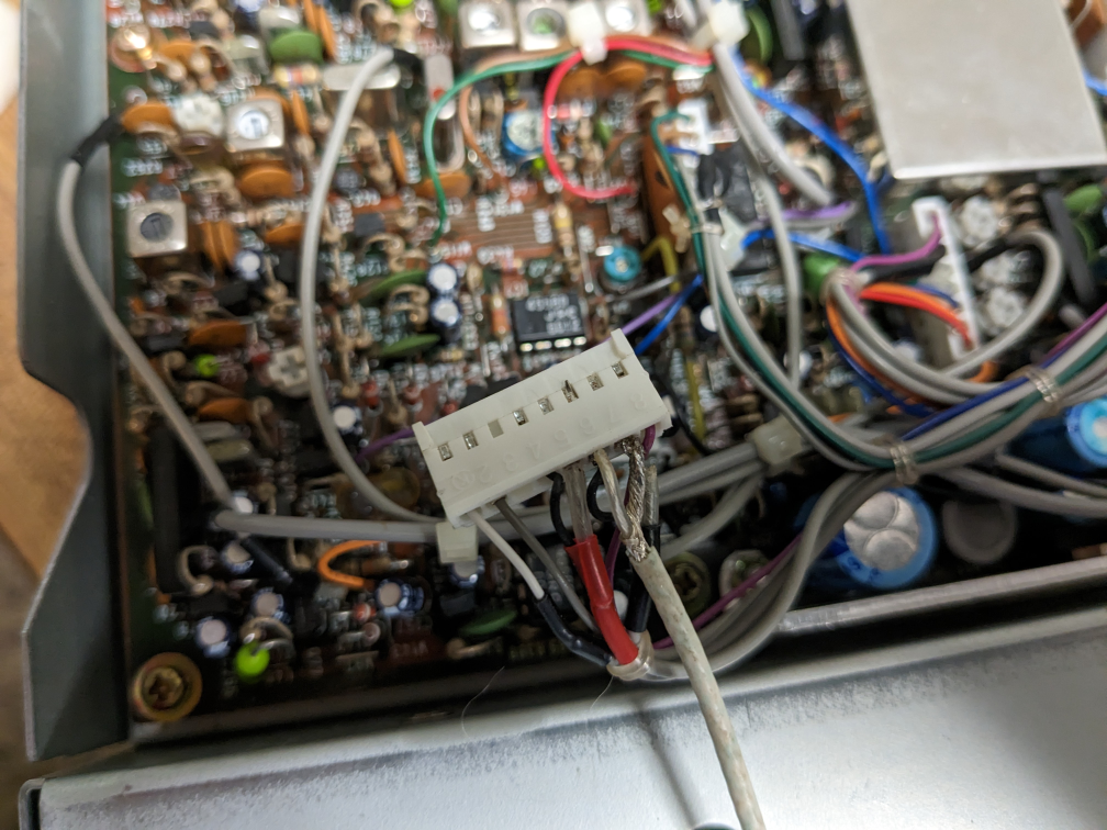
For the RX Out wiring, locate J15 Pins 6 & 7 (which is where the 24pin AUX audio Out is connected). I connected my cable in parallel with the wire going to the AUX connector; you could replace it if you have connector pins to make the connections to the new cable.
Serial Interface: If your radio doesn’t have one, get one! The good news is that Piexx makes a replacement for the long discontinued ICOM UX-14 option that is better than the original.
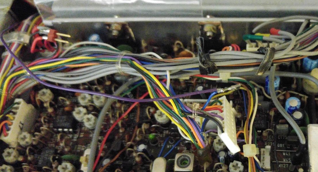

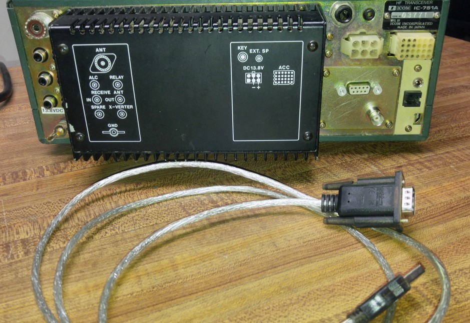
The new Piexx boards provide CAT controlled PTT and support reading the S-Meter. I’ve modified the FLDIGI rigcat IC-751.xml file to take advantage of these capabilities. If you wish to use the Piexx board’s PTT function, you can easily tap into the rig’s PTT line. The PTT line is called SEND on the schematic and can be found at J8 Pins 4 & 5. (You can find J8 on the schematic fragment shown in the picture above.) The pictures show the connection to the J8 header and wire routing. The S-meter connection is good to install as well, especially if you ever contemplate running your old rig remotely, which you could conceivably do with the serial connection and a remote desktop application.
RTL-SDR Dongle Connection: To add some real additional functionality to this old rig, attaching a $25 RTL-SDR dongle on the IF has to be the biggest bang for the buck that you can get.

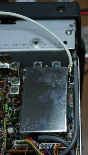
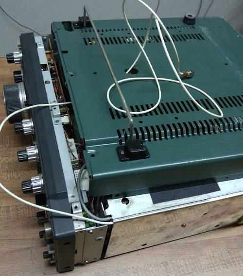
It is easy to do with the IC-751A. Just find the SCOP connector point and attach a piece of coax to go into the antenna port of the dongle. The pictures tell the story. There is a nice hole in the bottom cover that lets you get the cable out. Better yet, run the cable to a connector as shown below. Check out the RTL-SDR Pan-adapter using HDSDR with the IC-751A for the details on how to make this all work.
CW and PTT for Computer Keying: There are two ways to send CW. You can either set up the radio in side band and send audio generated CW sounds with a program like FLDIGI, or you can actually key the rig much like you would pressing down the key, but electronically.
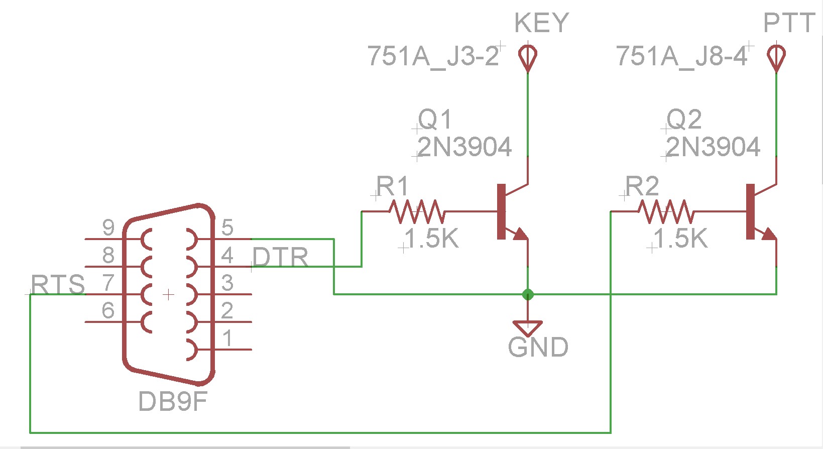
The audio method will work once you have configured the sound card connections. Some programs such as N1MM logger will not drive a sound card and you need to configure a TTL-level keying interface. The usual method is to use the control lines RTS and DTR on a serial RS-232 port from the computer. These days, USB ports are much more common, so a good approach is to plan to use a USB to serial adapter dedicated to the keying lines. The RS-232 standard toggles the voltage on the pins between about -10V and +10V, whereas what the key or PTT lines want is simply a switch to ground. Hence there needs to be a simple single transistor buffer between the RS-232 lines and the connections in the radio.
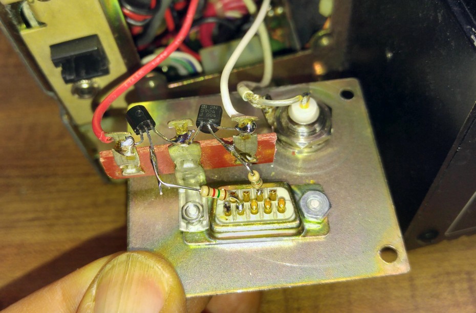
There is a small blank panel where the AC line connection would go if I had the internal power supply. I used that panel to mount a DB9 connector for the RS-232 connection. (While I was at it, I added a BNC connector for the RTL-SDR cabling described above.) The photos show how the little buffer circuit was built off of the connector. You can make the PTT connection to J8 Pins 4&5 as described above. For the KEY you want to connect to J3 Pins 1&2 (no photo). Originally I made the connection to the KEY jack on the 751A, but that required the electronic keyer to be turned off and it was not possible to have the paddles and the computer connection work at the same time. Using the J3 pins gets around this so that you can easily key with the paddles whenever you want.
Upgrade 30.72 MHz reference oscillator with an OCXO: The IC751A doesn’t drift too much, but I was interested in doing some long term dopplergram measurements where any drift is too much. The ICOM upgrade high stability oscillator, CR-64, is unavailable and expensive if you find a used one. However, on e-bay you will find many 30.72 MHz OCXO’s for about $25, mainly from China when I bought mine. I found a Vectron OX-220 series oscillator which merely needs 3.3 VDC to provide a very stable, few ppb, reference. The IC-751A doesn’t have much in the way of low voltage supplies, and the heater current can be up to almost 1 A during warm up, so I looked for a suitable regulator. The solution was the CUI P78A03-1000, a three pin switching regulator with 3.3V out and 90% efficiency for $4. Click on the figures below to see the modification I made. I lifted R6 to disconnect the power from the stock crystal circuit. The OCXO was mounted upside down with double stick adhesive to the cover of the PLL enclosure. The P78A03 was soldered directly to the terminals of the OCXO. A 2.2 Ω resistor was used as the wire to the 13.8V supply point. The RF was injected by soldering to the top lead of R7 with a 0.01 uF capacitor between the OCXO output and the injection point. Although the OCXO puts out a square waveform, the IC751A doesn’t seem to mind that.
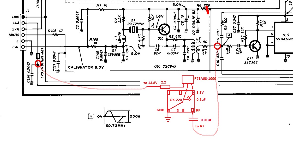

With the new reference oscillator running, the Calibrator is no longer functional or needed. The rig is now dead-stable and nuts-on frequency. Very nice!
You are ready to have fun!

Hi Gary, my name is Ash and I am from South Africa, I am a newbie with radios and just managed to get an icon ic751 and I have a rig expert sd, however I can get it to transmit but I am not able to get sound of my pc, any idea what would cause this
Hi Ash,
Best to remember that the IC-751 was built before there *were* PC’s, so the I/O can be cumbersome. If you are hearing sound from the speakers or headphone, then you should be able to get it on the rear “ACC” socket – Pin-4 – the ground next door on Pin8. Worth downloading a manual if you don’t have one… Good Luck.
hello gary, thank you very much for a great article. I just have a drift problem on an IC-745 and I can’t find a CR-64 at a reasonable price. I will therefore apply your experience, the two transceivers having practically the same PLL cards. it may be necessary to do the same on the 2nd LO board of the ic 745 which has a 10.24Mhz crystal which is in the cool air column of the fan. 73 of F4IGV
Yes, the IC-745 likes to drift when you pull cool air across the crystal. Certainly a real OCXO would help. Just be aware that there are two crystals that can contribute to drift with the IC-745 for the 1st and 2nd local oscillators. I believe on the IC-751A, there is no second crystal and the timing is derived from a single oscillator. You might want to try the Styrofoam peanut insulator fix (see the IC-745 blog post) before you go to al the work of replacing the oscillator(s). Good Luck,
I need your help with a Bluetooth mod on my Icom 751. speaker and microphone to Bluetooth box mod would be very helpful. I already have your USB cable mod to laptop
Hello Gary,
I am looking for J4 on my ic751a and found one with a cable already connected to the socket. The other end goes to the top side and is also connected to a socket. Is there another label for the SCOP connection?
I would like to use HDSRD with the rig.
Could you send a photo of what the actual connector looks like? I take it the cable is a sma type of coax cable?
thanks,
tony, KI6DOZ
Hi Tony,
There is a photo in the article that shows where the connector is, hiding behind the RF shielding box in the picture. The photo does not make clear that this is actually behind the RF cover on the RF section that is on the side of the unit. Remove top and bottom covers AND the RF cover on the side and then you will see what is in the picture. As I recall the little two prong connector was not used. Somewhere I found another female connector housing and made up a nice connection… you will have to be creative :)