
I’ve been using a spool of RG-6 CATV cable of dubious quality for quite a while as my go-to source of antenna feed line because I happened to have the spool in my junk collection. Using the 75 Ω cable got me thinking about why we care what impedance the cable is and how matching is really a two-sided affair. What I found through my own experimentation, and running numerous NEC models is that there is little intrinsic value in sticking to 50 Ω cable. The main advantage for using 50 ohm cable is that you don’t have to think much about the length of the cable run because, if terminated in 50 Ω at the transmitter, any wave reflected from the transmitter will be absorbed at the transmitter and not re-reflected, so its a one-way affair. However, as soon as you put an antenna tuner at the transmitter, this one advantage goes away; with the tuner the cable is no longer terminated with its characteristic impedance, so it will happily support standing waves.
What should affect your choice of cable? Here are my criteria in order:
- Voltage handling capability
- Cost
- Loss characteristics of the cable.
- Jacket Dielectric
- Characteristic Impedance
Cable Table

Lets start by looking at a co-ax cable chart. This is one I compiled over the years and have distilled to a few essential numbers to be better able to compare cables for HF and VHF applications. The chart is arranged in order of increasing cable size. What you notice in general is that the voltage capability tends to increase and the losses tend to decrease as you make the cable diameter bigger. However, there are exceptions to this general trend that relate to the specific form of the dielectric insulation used in the cable and the cable impedance. Lower impedance cable has a relatively larger center conductor than higher impedance cable. Hence you would expect slightly lower resistive losses on lower impedance cable. Solid polyethylene (PE) is commonly used when voltage handling is important, however, using foamed polyethylene (F-PE) will significantly reduce dielectric losses in the cable. In addition, it turns out that for a given outer diameter cable, if you increase the dielectric constant you have to make the inner conductor smaller to maintain the same impedance. Smaller inner conductor has smaller circumference and higher skin resistance. Hence the advantage for using foamed dielectrics with lower ε. For frequencies up to a few hundred MHz, the dominant loss mechanism is resistive loss in the skin current layer. The penetration depth of the current becomes smaller as the frequency increases, causing the losses to scale as the √f . At higher frequencies, the dielectric loss tangent comes into play and generates losses that are proportional to f. For the HF bands, using just the √f scaling will get you mighty close.
The F-PE dielectrics are almost more like air than plastic, so the speed of propagation is faster in those cables as well. If you are running 100 W or less, then just about any cable can handle the RF voltage including the foamed varieties. When running power you have to be more careful. RF and DC are different beasts; how well you make connections matters a lot when operating near the voltage limits of cables. Avoiding high SWR is also required to avoid voltage multiplication in the cable.
Playing around a little bit with LTspice, it is possible to model cable line losses, impedance mismatches, etc. The most important loss mechanism for the HF bands is the skin effect, which is modeled in my circuit as just a simple series resistance with a frequency dependence that varies as √f. Here is the model results for a one hundred foot run of RG-8X.

The typical power loss with increasing frequency is seen in the power delivered to the load (green). With the cable matched on each end with a characteristic impedance match, there is no unusual frequency dependent features that depend on the time delay in the coaxial cable. That situation is not the norm, as we will see when we discuss mismatches below.
CATV 75 Ω Cables
If cost is a driver in your choice of coax, as it often is, then one should look at CATV cable types. Thousands of miles of this type of cable has been manufactured, so the economy of scale helps us here. What matters to the CATV folks is not to have to boost the signal too much, so low loss is important at TV frequencies (VHF and up). To keep cost down, there is no copper in this stuff other than the coating on the steel center conductor, otherwise just aluminum. It is hard to find comparable low loss cables for less than at least three times the cost of the RG-6 and RG-11 aluminum CATV varieties. These cables are often not voltage rated at all or will declare a 300 VRMS rating. The best comparison is to look at LMR400 which is also a F-PE dielectric type and observe that his cable which, is about the same size as RG-11 types, is rated at 2500 VDC and good from 1600 W at 100Mhz.
The other issue using CATV aluminum cable types is making the connections. Fortunately, we have crimp connectors. It used to be difficult to find PL-259 type crimp connectors for RG-6, but now they can be found easily on E-bay from China. Crimp connectors for RG-11 are the same as those used for RG-8, are plentiful, and cost a couple dollars each. Some of the best CATV types are meant for burial and are “flooded” with a gooey gel to prevent water from wicking along the cable, and often have PE jackets.

Crimp Connectors
The figure on the right shows how I gauge how far to cut back the insulation using the actual connector as a guide. In the background is the GOO GONE I use to get rid of the flooding goo. Snip the braid back leaving just enough to extend over the connector ferrule. Then remove the insulation to reveal the center conductor. Electrically, the weak spot is break down from the center conductor, tracking along the cut insulation to the outer conductor. I increase that path a little by cutting back the foil so the breakdown track would have to go around the corner. I know some folks who taper the insulation into a cone for even better tracking resistance.

Now it is just a matter of sliding everything together and crimping. When soldering the center conductor on the PL-259, use a hot iron, and work quickly with the connector level. You do not want a blob of hot solder running down to the insulation, nor do you want to melt the insulation with too much heat. Get the solder on and then quench with a damp sponge.
Cable Jacket
Often the cable jacket has no electrical consequences. It is there just to protect the rest of the cable assembly and hold it all together. However, in some antenna applications, I like to use the outside of the outer conductor of the coax as part of the active antenna structure, and often will make coils wound of the coax as traps or chokes. In these circumstances, especially with coils, the jacket material can matter. There are two common choices for jacket material. Most common is PVC insulation, but you can also find cable jacketed with polyethylene (PE). What is curious here, is that PE is one of the very best dielectric materials with a loss tangent ~0.0002 whereas PVC is one of the worst dielectric materials with loss tangent ~0.1 ! Why does this matter? Image making a self resonant coil with the two materials. Much of the capacitance associated with the self-resonant coil will be due to fields in the jacket dielectric. The Q of the capacitor formed with such a dielectric is the reciprocal of the loss tangent, so with PE dielectric the potential Q is ~5000, whereas with PVC it is only ~10. In the worst case, where you are driving power into an antenna load terminated with a resonant trap, you could put a lot of heat into the insulation if it is made of PVC! Does this happen? I don’t know, but I’ll go for the PE jacket if I have a choice.
Feedline Coils – Traps and Inductors
This really is an article in itself, but I’ll just mention a few points here. If you are building a “resonant feedline antenna,” where you are defining the active antenna element with an inductor on the feedline, then Q matters. The reason is quite simple — you are driving into the end-defining inductor so any losses there are power losses. Hence the argument above to use PE dielectric cable, but also this should clue you in to be wary of using ferrite cores. Just as dielectric materials can be lossy, so can magnetic materials. An efficient resonant feed line antenna will use a high Q trap where both inductance and capacitance combine to give very high impedance at the operating frequency, rather than using a large non-resonant ferrite inductor.
If the point of the feed line inductor is only to block RF currents from coming back to the transmitter, then then you do want to use the ferrite core inductor and should not attempt to block feed line RF on a multi-band antenna with an air core coil. Losses in this application are your friend, since any RF bouncing back and forth on the way to the transmitter is unwanted. The narrow band, low inductance, nature of air-core coils tends to make them useless very far from their natural self-resonance.
Modeling shows that two modest size inductors spaced a distance apart are better at killing feedline currents than a single large inductor. This is because the single inductor can define a current null at the inductor location, yet allow a resonant mode to persist on the remaining length of feedline. Defining two locations for RF current zeros much more effectively eliminates feed line resonances.
Feedline Mismatch and Length
What really goes on when you have a mismatched load, finite lengths of cable with their associated losses, various cable impedances, and lets throw in an antenna tuner to complete the picture? To put all of this together, I’ve been playing with LTspice models of various feed line configurations. What I’ve found is worthy of another article, so I’ll just touch on some results from a couple models to wet your appetite.
With multiband dipole antennas, such as GR5V and OCFD designes, the feed impedance at the antenna is often significantly larger than 50 Ω, often between 100 Ω to >200 Ω for some bands and designs. A section of mismatched cable is much like a tuner in that it can reduce the SWR in the feed line if adjusted correctly. The figure below illustrates what happens when you have a simple mismatch; in this case in the load is 120 Ω, a value that places the 75 Ω cable, plus its losses, at about the geometric mean of source and load impedance. The SWR is the brown curve which you can see approaches 1.0 at several frequencies.

At other frequencies, where the SWR is highest, the source and load voltages (red and blue traces) are identical, almost as if the cable was not even there. These extremes are at odd 1/4 wave multiples or 1/2 wave multiples respectively, of the waves that fit on the transmission line’s electrical length. The periodic frequency dependence is the result of fitting the next half-wave on the transmission line. There are a few “good” transmission line lengths that will tend to have SWR minimums for more than one ham band. The 122 ns electrical length (36.6m electrical = 30.38m of VF 83% cable = 99.7 ft.) generates happy minimums for 30m, 20m, and 17m ham bands. Note that if you were running a 50 Ω line to the 120 Ω antenna load, the SWR would be about 2.4; the mismatch of the 75 Ω cable and the 120 Ω load has SWR 1.6. In general, using the intermediate impedance cable , between source and load impedances, can only help with the power transfer efficiency.
As a final example, here is the case of 50 Ω line driving a bad mismatch, SWR 10, but with a tuner at the source. In the example the tuner is adjusted to deliver power to the load a about 14 MHz, which you can see by the low SWR at the source (brown) where it almost touches 1.0 near 14 MHz on the graph..
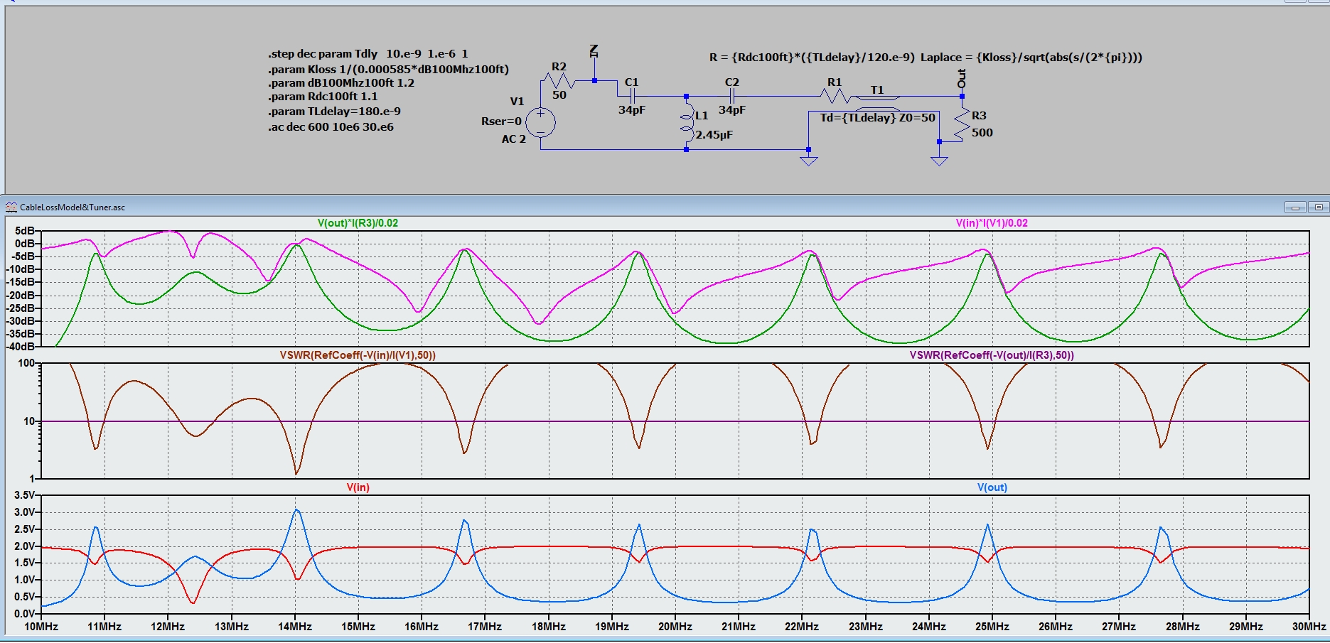
What you can see by all of the resonances that show up on the frequency plots is that there are plenty of standing waves on the coax when there is a tuner between the 50 Ω source and the 50 Ω cable. Where the tuner allows the source to be well-matched at 14 MHz, the input voltage (red) is properly loaded to about half the open circuit voltage of the source. Notice that into the mismatch, the output voltage (blue) is more than three times that matched voltage (1.0 V as modeled). The input (pink) and output power (green) are normalized to the matched case. Note that maximum power transfer does indeed correspond to the low SWR point where the green and pink curves kiss. Somewhat surprisingly, the power transfer to the load is very good where tuned, despite the high SWR at the load. There are other frequency values where the power transfer is not too horrible, where the feed line resonances allow it. As you can see, there is nothing magic about 50 ohms!

I’m still a novice at this stuff, but one thing I’ve read and heard is that a tuner can deceive you as to the SWR. In the case you show in this article, doesn’t the standing wave on the transmission line cause additional losses which wouldn’t be shown on your rig’s SWR meter?
This question is especially interesting for the end-fed half wave type antennas. The traditional way to build these was:
1) cut a “random wire”, which was really chosen at a length that was not resonant at *any* of the bands you want to use,
2) create a 5:1 balun, 5 turn side to the antenna,
3) and then use a tuner between the radio and the balun.
I have used this setup successfully. However, the downside of this is that the tuner may be creating large standing waves on the balun, which is of course lossy given the 25:1 voltage step-up is pretty extreme. How much this loss really is in a real-world case I have no idea.
The alternate, which seems popular lately, is the resonant end-fed half wave design using a 7:1 balun, and which doesn’t have a large standing wave on the balun torroid.
Am I thinking about this correctly?
P.S. Your tip about the difference between PVC and polyethylene when creating a cable coil inductor is very interesting, I’ve never seen that pointed out before!
Hi Daniel,
I don’t have a lot of experience with end-feds, but here is my 2 cents. The local wave impedance on any antenna wire is the ratio of the electric field (voltage) to magnetic field (current) at that point. At the end of the wire, the current is going to zero (it is exactly zero and the very end since there is no where for the current to go) and the voltage must be near a maximum at the ends. So you have a very high impedance situation. The only way you can push current onto the antenna wire is to do it with relatively high voltage — hence the step-up transformers. Q is the concept of how highly tuned a circuit is and is basically a a ratio of the reactance of the circuit to the resistance. High Q circuits have very low real resistance compared to the reactive components. When you feed the end of the antenna with a very high impedance, That is going to generate a relatively low Q situation. That means that there is no real strong peaks for resonance. This can be a good thing, because a broader resonance means you are cover more of the band. But don’t think that your “random” wire will not have frequencies it likes to sing and others that it doesn’t. Ii is usually a good idea to get “close” to a half-wave integer for the bands you want to play on.
What your tuner is going to do is allow you to adjust the voltage/current phase relationship a little so that even if the physical length of the wire is not right on the target resonance, you can get it to work. If your tuner “does something”, then you indeed are finding a resonance on the wire.
Efficiency can be good and losses pretty low with a well designed balun. With end-feds, I would expect that you would have to be more careful with dielectrics and breakdown since the energy at the feed is mostly in the electric field. A good way to get a feel on if you need to worry about SWR losses is to try and run your antenna without a tuner and see if you can measure the SWR. If it is more than ~5 then you will start getting excessive cable losses as the wave bounces back and forth between tuner and balun.
Good Luck!
With respect to the “random wire” design, the goal is to choose a length of wire that is far from resonance on all the bands you want to cover. Then you use a tuner so that the tuner/balun/wire system is resonant for each band. The reason for this is that most tuners can’t go much more than a SWR of 10. You choose the balun design so that it will bring SWR under 10 for all the bands of interest. However, if you’re too close to resonance on any of the bands, there will either be >10 SWR for those bands if the balun doesn’t match them, or >10 SWR for the non-resonant bands. At least that’s my understanding of the concept. Professionally I’m a chemical engineer and programmer, I just dabble in electronics and radio as a hobby.
Thanks for the insight!
End-fed designs are quite interesting to me because I like ultra-portable operation, and they are the lightest possible HF antenna designs. There are 10 watt designs where the entire antenna including wire and balun can fit in the palm of your hand. There have been HUGE debates over the years in the ham community, some quite heated, about this topic. For example, many people insist that you *must* have a counterpoise for such a design to work. You don’t – many hams including myself do not use a counterpoise, and in fact field tests often show that adding a counterpoise reduces performance. Then there is then the question of what even counts as a counterpoise – depending on how you build it the coax shield on the short line from the radio to the bulan may be acting as a counterpoise! There are also apparently some quite subtle effects around capacitance and inductance in the torroid and windings of the balun for this design which I honestly don’t understand. I know the torroid construction is absolutely essential, I tried building one with the wrong type (even though it looked the same), and almost no signal got through at all.
As I was pondering this, I realized there may be another issue that could cause resonant EFHW designs to work better than “random wire” EFHW designs. My understanding is that because you’re stepping up the voltage to such a huge degree, you have to worry about magnetic saturation of the balun torroid. As a result these designs are normally only rated for 10-100 watts. Even the 100W designs require a massive double stacked torroid. If you’re putting a standing wave on the torroid, wouldn’t that saturate the torroid at even lower power?
Hi Gary, I love your blog, a great, down-to-earth and practical approach to fiddling with antennae, which remains a black art to many. I have a couple of questions:
1. Regarding 75 ohm feedlines and odd quarter wavelengths thereof: Much has been written about the (potential) virtues of 75 ohm line, its low cost, its ubiquity, and so on, but the issue of matching to 50 ohm radios always comes up. Why not just install a broadband ferrite 1:1.5 transformer at the radio and carry on?
2. Regarding 4nec2, do you know of any comparable software for Mac or Linux so that those of us not afflicted by Windows might play?
Best 73,
Larry, NM7A
Hi Larry,
Certainly you could use a 1.5:1 matching transformer but — then you don’t get the benefit of using the 5/50 ohm mismatch to your advantage. I do this a lot with the vertical collinear designs because it is possible to make the natural wave impedance at the antenna end close to 125 ohms which works out to be close to a match into 50 ohms with the 1/4 wavelength 75 ohm line in between. If you have an antenna tuner in between anyway, then you also don’t need to bother with a transformer, just let the tuner do the job. It really comes down to why you want the 50 or 75 ohm cable in the first place. IF it is to match a nice multiband yagi that is designed for 50 ohms — that might be a good reason to use 50 ohm cable. But once you put an antenna tuner in the path, there is very little reason to be wedded to 50 ohms. I’ve got some relatively long cable runs. One 1000′ spool of RG11 for $250 will be all of the coax I will ever need.
Regarding 4NEC2 — I’ve heard that EZNEC is now in the public domain. That might be a solution. Not sure if it works on Macs or Linux. ALso not sure it it can do all of the optimizations and parameter sweeps you can do with 4NEC2… But there are other programs out there if you look around…
73, Gary