
I have had a chance to use HDSDR a little more with the RTL-SDR pan-adapter for my IC-751A transceiver and have found it a very nice tool for a number of applications. Here are a few examples.
Pan-adapter for rapid SSB tuning
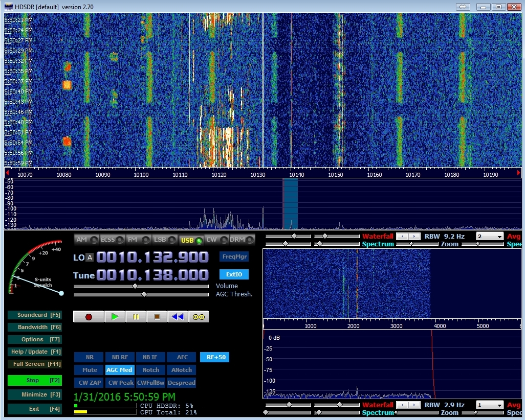
This is the obvious application. Using the RTL pan-adapter with HDSDR set to “Full sync in both directions,” it is possible to monitor the entire ham band for SSB signals and to tune the parent radio to the transmission by clicking on the signal in HDSDR window. The received signal can be heard either through the parent radio or demodulated with HDSDR. Either the RTL-SDR or the conventional receiver might sound better, depending on the quality of the parent receiver. The filter edges are very steep and simple to adjust in HDSDR, and there is a very sharp notch filter that can remove unwanted narrow-band signals that might be contaminating the voice channel. Nevertheless, to my ears the wider audio notch in the 751A seems to provide more readable and comfortable voice signals.

The HDSDR screen shot above shows more than a dozen voice signals to sample across the 20 meter band. One of the nice features of this program is the easy way to set the squelch with a click on the S-meter. A curious digital mode transmission is in progress just above the ham band at 14.366 MHz. For the voice modes, the frequency synchronization and stability between the parent receiver and the RTL-SDR radio is plenty good enough that your transmitted signal will fall on top of the HDSDR frequency settings (once you have it all set up correctly) if you are listening using HDSDR.
RFI identification and signatures
The big view of the pan-adapter can show more than just intentional transmissions. In the screen shot below you can see the situation on 30m this afternoon. The wide view makes RFI problems unequivocally show their presence. Below you see a strange on/off modulated RFI signature every ~17kHz across the band. RFI can come in many forms. Switching power supplies can generate bands of noise spaced at uniform frequency intervals. One of the next projects here will be to set up a portable RTL-SDR computer rig for chasing down such RFI sources, which can plague reception especially on the lower bands in my neighborhood.
Working the pile-up
To the left of the center of the waterfall above you can see a pack of CW operators in a “pile-up”, all looking to contact a rare DX operator. In this case a “DX expedition” to the South Sandwich Islands is the attraction. Breaking through the pile-up is an art that I have yet to master, but I can see that the wide view of the pan-adapter can be invaluable to help identify the actual station of interest in the midst of the hoards of other signals seeking attention, as well as the frequency where the operator is listening by identifying where in the pack the selected stations are replying. If the DX station is working “split,” outside the 3kHz bandwidth of the 751A, picking the correct place to call can be purely guess-work without the wide-band knowledge.
Monitor SSB net while working PSK on the parent radio
The are many examples of “doing two things at once” that can be accomplished because of the ability of HDSDR to be tuned independently of the parent receiver. For starters, tune the transceiver to the PSK portion of the band. Select independent tuning for HDSDR. Configure the audio output from HDSDR to the computer speakers and go hunting on the voice section of the band. Listen in on your friends while you use FLDIGI to work the PSK section of the band with the parent transceiver.
Monitor the JT65 & JT9 band while working PSK – or vise versa
It is possible to run two digital-mode decoding programs, one for the parent transceiver and one for the RTL-SDR receiver tuned through HDSDR. Yes, you will have three radio programs going at once! Sometimes it is not possible to get everyone to CAT correctly – so here is my general plan. The working application will be connected to the transceiver audio in the conventional manner, and will be controlled from HDSDR using the “CAT to HDSDR” port via a Virtual Serial Port (VSP). The monitor application will get it’s audio from HDSDR via a Virtual Audio Cable. You will have to manually tune this monitor application to match the HDSDR tuning since the working applications is using the “CAT to HDSDR” port. Use “independent tuning” so that the HDSDR’s LO control tunes the transceiver and the working application, while HDSDR’s Tune control tunes the monitor application. Below are step-by-step instructions for setting this up:
- Configure HDSDR and Omni-Rig to CAT to the transceiver.
- Set up a Virtual Serial Port between “CAT to HDSDR” and working program you will be using to work contacts, e.g. FLDIGI.
- Set that program up to accept VSP connection as a Kenwood TS-50 as HDSDR requires.
- Test that you can control the rig and HDSDR via the working program, FLDIGI for example. Changes from the rig will reflect back to HDSDR which will then make the changes to FLDIGI. Similarly going the other way, HDSDR is in the middle.
- Set HDSDR sync mode to “independent tune in HDSDR.” Note that tuning the LO frequency control will change the transceiver frequency.
- Bring up the monitor application, e,g. WSJT-X. Set up for no CAT control.
- Connect the monitor application to HDSDR audio output using a Virtual Audio Cable.
- Tune HDSDR to the band section you wish to monitor. Manually tune the monitor application to the same frequency.
- Go back to the working application and make some contacts. You can tune around the band with the working application all the while the monitor application remains at the desired frequency. However, if you change bands you will have to re-tune the monitor application.
I almost always try to work stations with audio routed to/from the transceiver in the conventional manner. It is possible to listen to the RTL-SDR / HDSDR demodulated audio, and then transmit using the parent transceiver. However, my RTL-SDR dongles do not have the frequency stability that allows me to know for sure that I will be exactly on-frequency. A frequency shift of just a few Hz between Rx and Tx can lead to confusion with digital modes. Using “split” modes can help deal with Rx/Tx discrepancies.
Leave the radios on and monitor PSK, RTTY, JT65 & JT9 traffic for PSK Reporter
You can use the set-up above as a much more complete digital-mode band monitor. Set the applications, e.g. FLDIGI and WSJT-X to report spots to the PSK Reporter website. JT65 and JT9 spots are the most productive, but there are plenty of PSK signals as well that might be of interest that FLDIGI can flag. Once your spots are logged to PSK Reporter, you can quickly see what parts of the world you are hearing via the PSK Reporter website map.
I’ve also used RCKskimmer, to monitor the band for RTTY and PSK31 & PSK63 signals. If RCKskimmer is looking at the RTL-SDR radio tuned through HDSDR, then you can skim signals from the PSK and RTTY sections of the band. Meanwhile, the transceiver can be tuned on the JT65 region. Again, all spots can be sent to PSK Reporter.
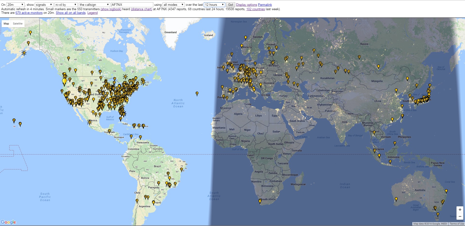
Using these techniques you might be amazed at what your antenna is picking up when you otherwise are not actively listening. I’ve started using WSJT-X 1.70 recently which has a much better decoder than previously. I’ve seen more than two dozen signals simultaneously decoded when looking at the full JT band with the RTL-SDR using the new WSJT-X. The screen shot below shows typical activity seen on 20m over a few hours monitoring both the entire JT65 & JT9 bands and the PSK band. If I keep the radio on I reliably end up in the top 20 monitors in the PSK Reporter statistics despite my out-of-the-way location in the Pacific Northwest.

Hi Jay,
I have made an IF connection to an Icom IC 725 rig. I feed this into the antenna connector of my RTL-SDR and uses SDR#. If I tune to the right IF frequency on SDR#, and get the gain setting right, I should be hearing the signal I am tuning on the IC 725 on SDR# without any further piping or feeding into a sound card. Is that right because I have not yet heard anything. It also seems that the IF signal I should tune to in SDR# changes depending on whatever frequency the ICOM is set to? Can I somehoew contact you directly by e-mail?
73 Henry ZS3HA
Henry, I think you will have better luck with HDSDR. Try that. I sent you and e-mail so we can discuss this further.
The IC-751 has a receiver output port on the back of the radio. Why not use that instead of tapping directly into the IF?
Hi Doug, There is a Transverter jack, RX antenna input, and RX antenna output (from TX antenna), but nothing that gets you into the IF. The R820T2 RTL-SDR chips work from about 20MHz to 1.7 GHz but will not natively cover the common HF ham bands so you must do some mixing somewhere. The 70MHz IF is perfect for the RTL-SDR and allows the RF front end and BP filters to condition the signal before going to the dongle, which is also good. The beauty of the HDSDR control is that you can make the software work with the native 751 if you have CAT control…
I have SDRPlay RSP-2 that covers 1kHz to 2GHz with built-in pre-select filters and up to 10 Mhz bandwidth. http://www.sdrplay.com/docs/161115%20RSP2%20flyerV3a.pdf
I’m also using an antenna with a good match on all HAM bands from 80 to 10 meters (no tuner needed). I have CAT control of my IC-751 with Omnirig and HDSDR.
I’m using an MFJ-1708 TR switch which allows the SDR to share the antenna with my transceiver. I see two problems with this setup. 1) The MFJ doesn’t provide perfect separation so any time I transmit the SDR gets hammered pretty hard and 2) the extra connectors and complexity introduces noise from local sources.
Having said that, would you recommend tapping directly into the IF, using the RX antenna port on the back of the radio, or leaving it as it is?
Hi Doug, Looks like a nice SDR RX. With the built-in preselector and filters, there is little reason to use the 751A IF. When you transmit, it will be difficult not to hammer just about anything on the same band without added measures. I suspect you don’t need to worry about damaging anything with the MFJ switch in there. Does the relay trip on the 751A PTT signal?
The RX antenna port on the back of the radio is for an RX only antenna INPUT – not an output for your SDR. I’d leave it as it is…
i have been having great luck using my Signalink USB box for digital modes with my Icom 751.